


Hello,
I'm using the TLC5926IPWPR in a design. The TLC5926IPWPR chip is on a separate PCB than the MCU that is controlling it. The Clock and SDO pin must go through a cable about a 1ft long. I want to clock this as fast as possible, and I wanted to get TI's opinion on my clock signal. The cable is affecting it quite a bit and I wanted to make sure I meet the minimum requirements, as this design will go into large quantitty production and I don't want 1 in 1000 units to loose a bit or something.
Also note that I have two of the TLC5926IPWPR cascaded.
Here is my clock without the cable from the MCU IO pin: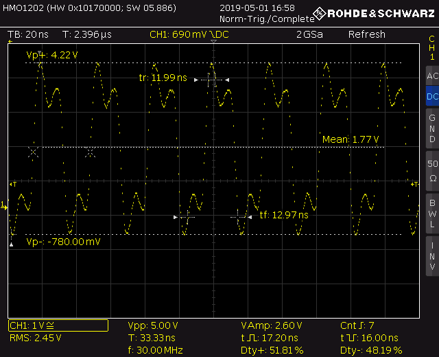
Here is my clock with the cable:
If I measure the time between the threshold of 0.7*Vdd and 0.3*Vdd, I get about 18nS. Is this the right way to measure the clock width requirement? It's the same time if I measure from 50% of Vdd as well.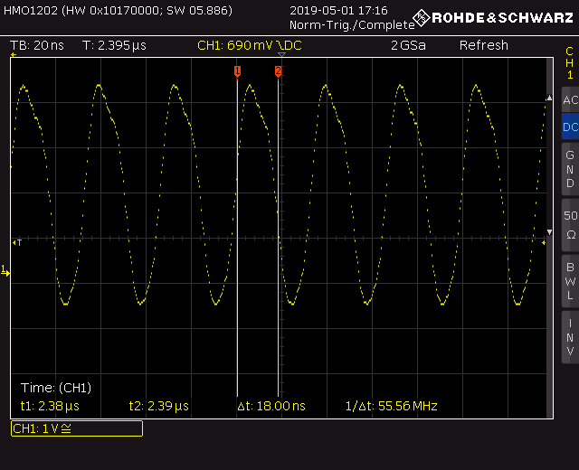
Questions:
1) If the max clock is 30MHz, why is the min clock width 20ns? Shouldn't it be (1/30MHz)/2 = 16.67ns or less?
2) My clocks rise time is well under the maximum, but what about the clock width requirement of 20ns min? Is my clock sufficient?
3) Any ideas on how to clean this up so it matches the requirements better at 30MHz?
4) Does TI have a schmitt trigger or something that could clean the signal up from the MCU to meet the requirements?
The chips are working great and I don't see any issues, but one unit is hardly a valid test of that.
Thanks for any help.
