This thread has been locked.
If you have a related question, please click the "Ask a related question" button in the top right corner. The newly created question will be automatically linked to this question.
Sitara Friends & Family,
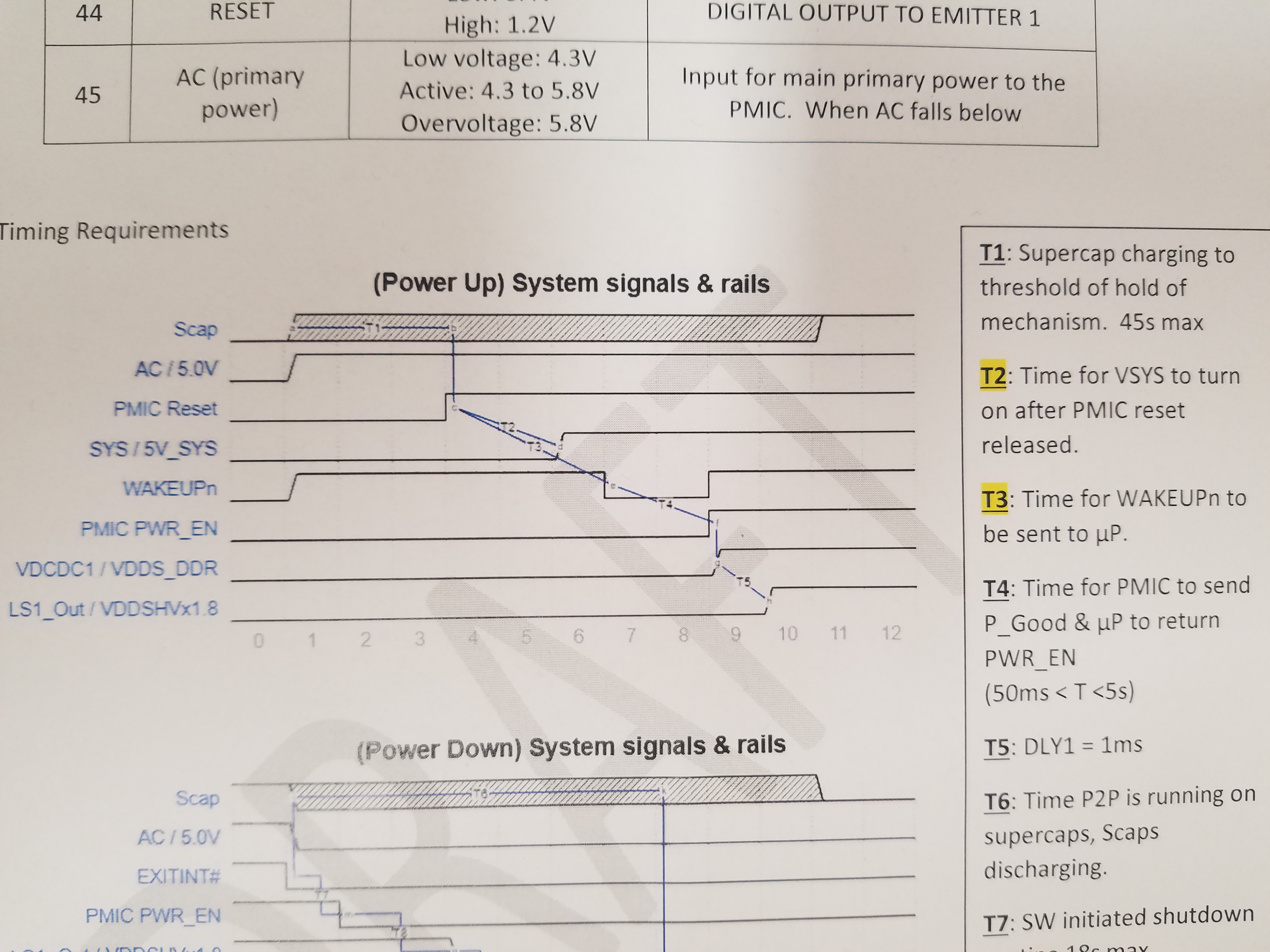
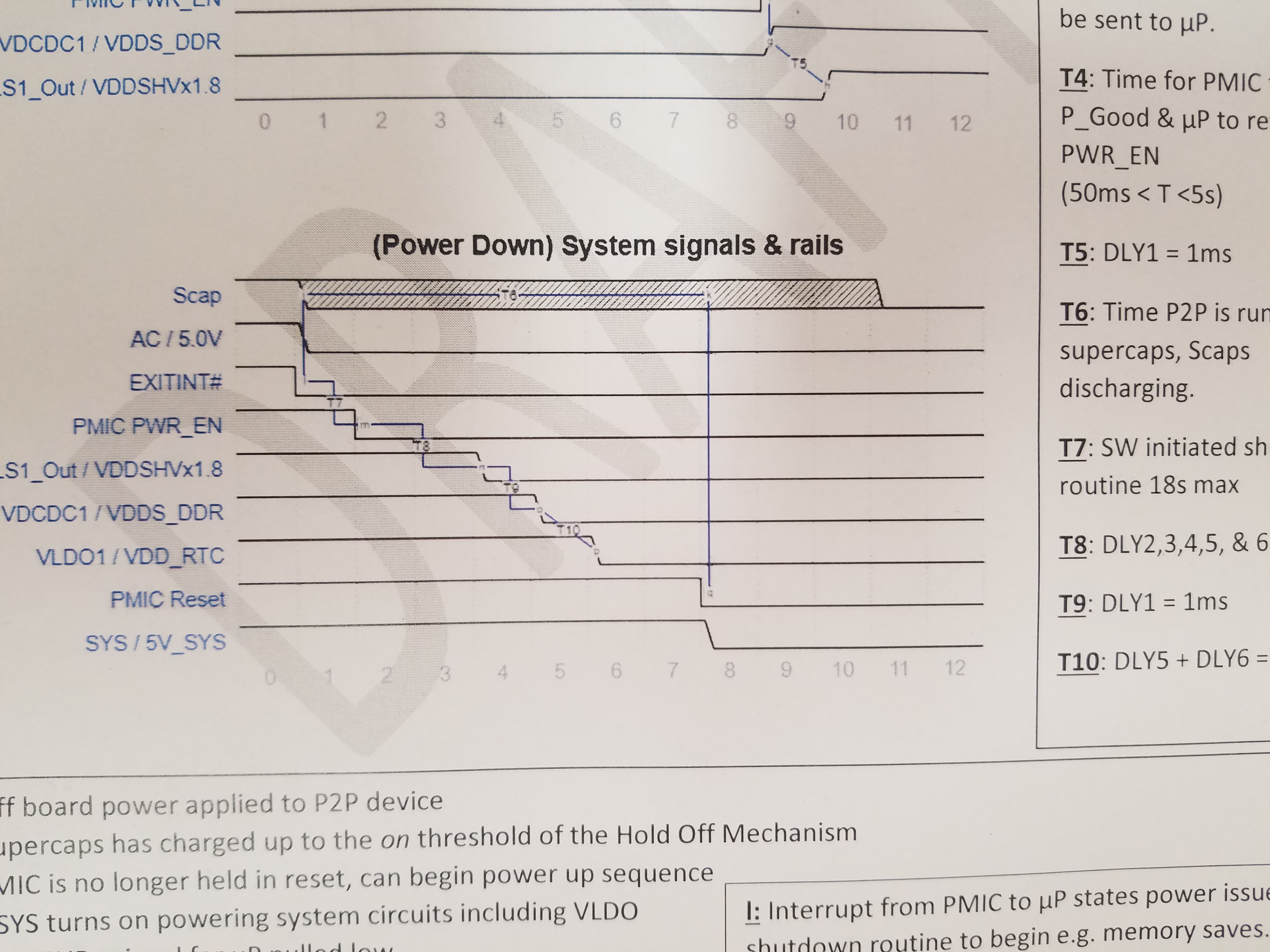
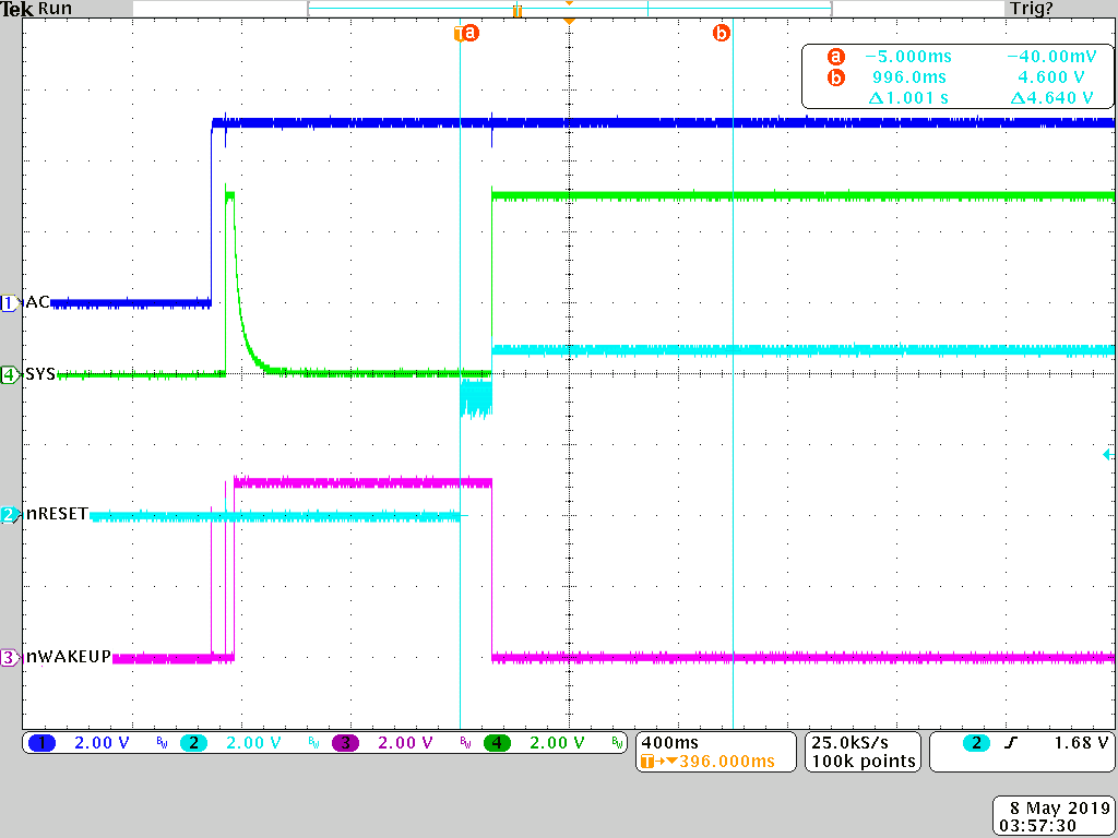
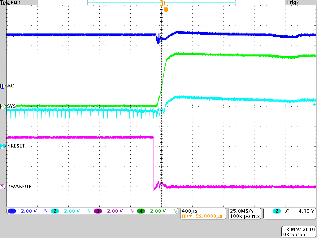
Our customer has a question regarding Timing Specifications between our AM335x Sitara and corresponding TI PMIC (TPS65217). See the below graphic which contains timing info per our specifications for most parameters, EXCEPT for that listed for T2 and T3:
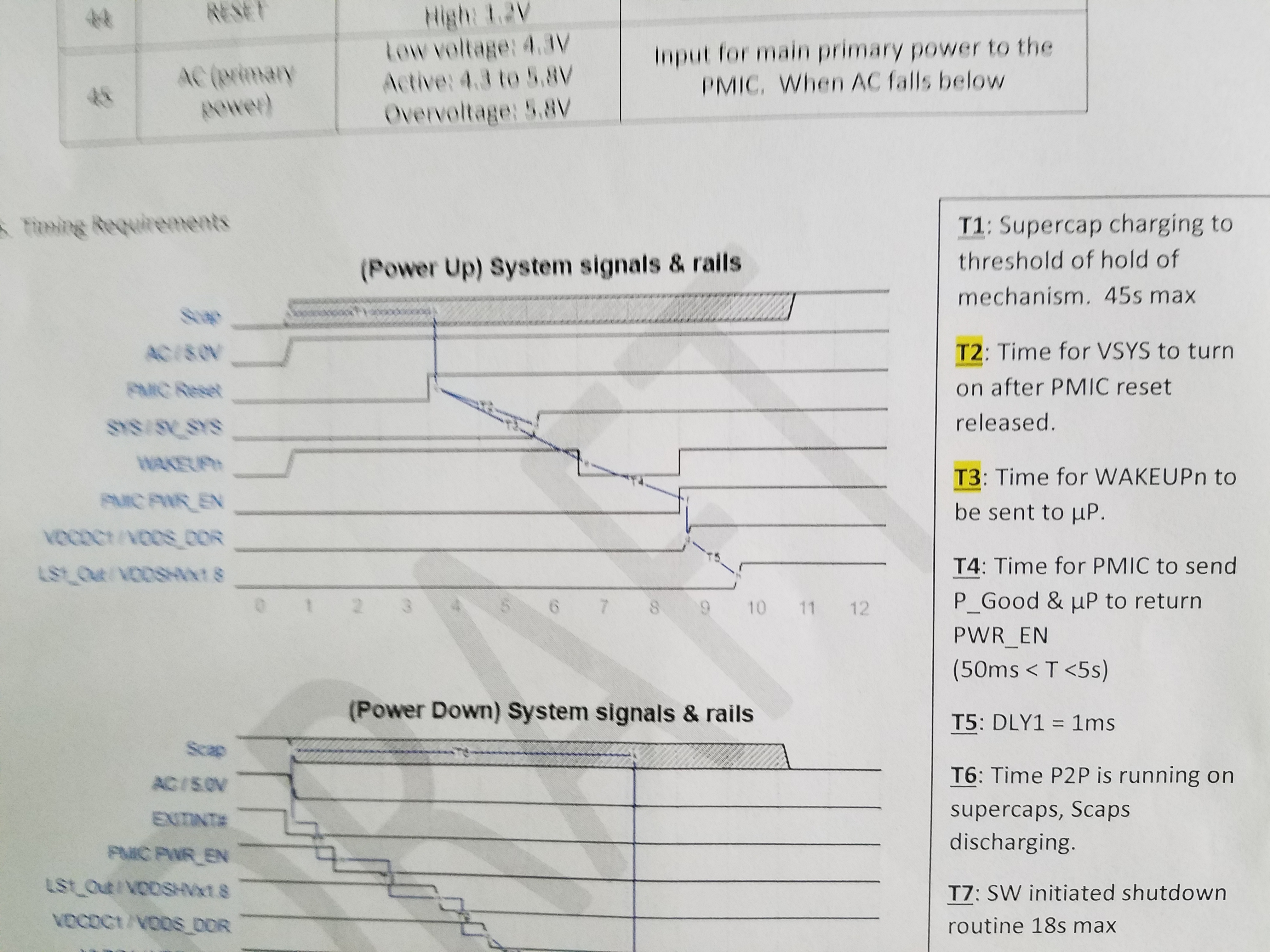
Can we offer a Timing Spec like we do for some of the other parameters (T1 T4 etc) such as 50msec < T < 1 Sec) for instance?
Also, please confirm that the nmi_int register location is indeed : 9C0h as defined in AM335x TRM.
TY,
CY
Thanks Brian! Very helpful. We’re getting closer but their SW resource is still unsure how to define the pins in the device tree. I realize this probably needs to revert back to the Sitara Processors Forum but perhaps Biser & Co can comment also.
There was a patch to the device tree to support the TPS65217. I’m thinking we need guidance on how to read the device tree and look for how it hooks to the kernel. Thanks again for your help or from others in advance.
Regards,
Chris
Chris,
It looks like a new thread was created and Resolved already. I will Close this thread. It will re-open automatically if you still have a related follow-up question.
The time from nRESET released high to SYS turning on can be anywhere from 30ms (tDG,nRESET) to 1s. The reason is because the RESET state in the state machine is a 1s loop. Every time the 1s timer expires, the state of nRESET is checked. If nRESET == Low, the PMIC stays in RESET for 1s more. If nRESET == High, the PMIC begins to transition to the ACTIVE state.
These pictures show a condensed version of your power-up sequence, showing the PMIC turning on after nRESET is released high at different points in the 1s loop.
There is no delay from when SYS goes high to when nWAKEUP goes low, as shown in this scope shot.