This thread has been locked.

If you have a related question, please click the "Ask a related question" button in the top right corner. The newly created question will be automatically linked to this question.

LM5022: LM5022 for Pout>100W application

Part Number: LM5022
Other Parts Discussed in Thread: LM3488, LM51551, LM5020

Hi,

I'm in midst of evaluating LM5022 use case on high power boost converter whereby my boost converter with 12V to 24V input targeting output power of 150W. I'm planning to use this device to replace LM3488 on my existing design. How does these two devices compared to each other & will LM5022 be a better suite for my use case? Thanks.

Regards,
Leo

  • Hi Leo,

    They are actually similar, and I don't understand your motivation behind the swap. Their driver are basically the same strength, and the LM5022 actually has less efficient current sense: 0.5V max for the LM5022 vs 0.15V max for the LM3488. On the other hand, the LM3488 does not have the soft start control.

    Instead, I will recommend the LM51551, our latest boost/flyback controller. It has lower current sense working voltage, hiccup mode under current limit, stronger gate driver, and some other improvements vs both LM5022 and LM3488.

    Thanks,
    Youhao Xi, Applications Engineering
  • Hi You Hao,
    thanks for the input!

    One more question: Is there any duty cycle limitation on LM5022 or LM3488? We observed that the LM3488 at high load (Iout = 6A, Vout = 24V), the duty cycle seems remain around 50% (Vin = 12V) in lab test. Will similar case be applicable to LM51551?

    Regards,
    Leo
  • The LM3488 does not have an effective duty cycle limit.  The LM5022 has some limit but datasheet only gives min 90% and 95% typical, and the max is not given.

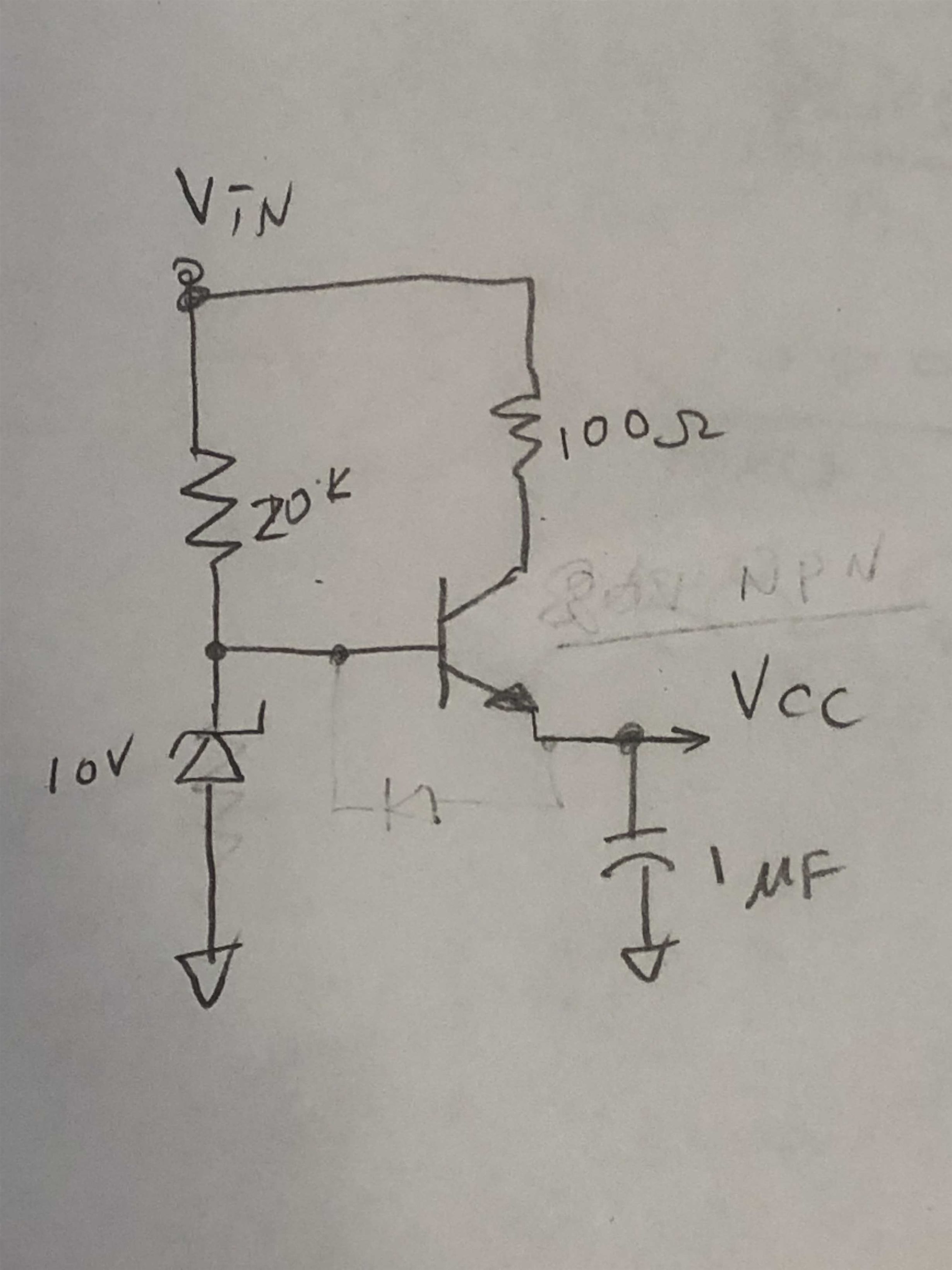
    We do have a device the LM5020-2, which has a fixed max duty cycle of 50%.   Because it requires min VIN=13V, you may need to use an external linear circuit to create 10V to feed that to VCC directly.  In this way, you can tie VCC with VIN pin.

    A linear circuit can be implemented with a 10V zener, with a bipolar (See attached hand drawing concept). Then you can put the LM5020 FB to GND, and the circuit will operate with 50% duty cycle.

    Thanks,

    Youhao