This thread has been locked.

If you have a related question, please click the "Ask a related question" button in the top right corner. The newly created question will be automatically linked to this question.

BQ24160: Battery is not charging in default mode

Part Number: BQ24160

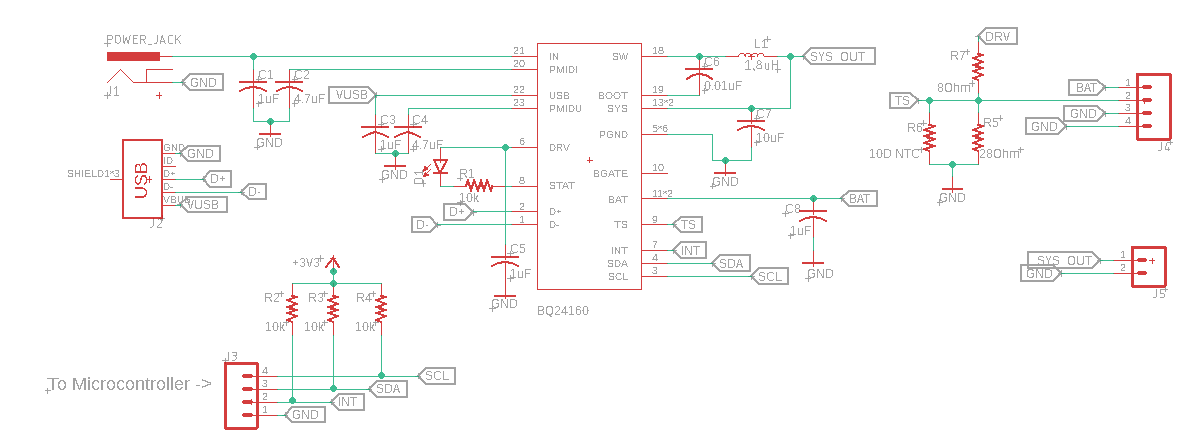
I'm using BQ24160(Not BQ24160A) to charge a 18650 3800mAH battery. I have not connected any of the I2C pins, to anywhere. Not even pulled up.

I'm also not using a external discharging FET.

A thermistor is added to the circuitry with the calculated resistor divider circuit.

I'm supplying 5V 2.5A to IN.

Once a battery which has a higher voltage than 3.6V, the SYS output gives the battery voltage and once it goes lower than 3.6V, IC regulates the input voltage to around 3.7V as the usual default mode characteristics.

But the battery is not appears to be charging. I'm using my laboratory power supply to give mentioned voltage above( 5V 2.5A). The circuit only draws around 10 to 20mA when a load is not attached  to SYS output and only a battery is attached to the BAT output.

My problem is where have I gone wrong and what can I do to make the battery charge.

  • Hi Kasun,

    The default battery charge voltage is 3.6V. If your battery drops below 3.6V, does it charge? If so, then you will need to use I2C to charge the BATREG register to 4.2V (as well as send the watchdog pulse to prevent reset).

    Regards,
    Jeff
  • Hello Jeff,
    The answer for your question is a "No"
    Battery is not charging even it's voltage drops lower than 3.6. That's the problem

    Thank you,
    Kasun
  • Kasun,

    Charge is reduced/disabled if TS pin is outside HOT/COLD window or VINDPM is active (meaning input at IN/USB pin has drooped to VINDPM treshold).

    Regards,

    Jeff

  • Hello again Jeff,
    I had the thermistor in my circuit from the very beginning. After you pointed out about the thresholds, I double checked my resistor values in resistor divider. They are Okay.
    But I'm not familiar with, why the input voltage is drooping to the VINDPM threshold.
    Do I need to stabilize my input voltages more? Or should I add a valid load(Coz I'm testing this circuit without a load)? or are there anything else to address this particular issue?

    Thanks
    Kasun
  • Kasun,

    To confirm, you measured the voltage at IN/USB pin and it has drooped to the VINDPM level?  Also, you measured the voltage TS pin and found that it is approximately 1/2 of DRV voltage? 

  • Jeff,
    I used my multi-meter to measure VIN. It says 5V is there.
    And also Yes, the TS pin voltage is approximately half of DRV pin.

    And also I was able to read the I2C registers. All the registers says that there are no errors of an kind, and in Battery/ Supply Status Register, INSTAT1 and INSTAT0 bits responds to plugging and unplugging of VIN with 00 and 11,

    But what I noticed was, even if I remove or change the battery, the BATSTAT1 and BATASTAT0 bits are not responding. it always in 00 state, which is battery present and normal

    Thank you

  • Kasun,

    Can you send me all the register values?

    Regards,
    Jeff
  • Hello Jeff,

    Here are my register values. And also I have attached my schematic diagram for the reference(CD pin is attached to ground).

    When only the battery is connected(No VIN or USB IN)

    ADDR    Value(MSB->LSB)

    00            00000000

    01            11110000

    02            10001100

    03            00010100

    04            01000101

    05            00110010

    06            00000000

    07            00011000

    When the battery and VIN is connected

    ADDR     Value

    00            00010000

    01            00110000

    02            10001100

    03            00010100

    04            01000101

    05            00110010

    06            00000000

    07            00011000

    Regards,

    Kasun

  • Kasun,

    The registers report VBATREG=3.6V so the charger will not charge if the battery is above 3.6V. Also, on the schematic, your TS pin resistors are very small. What is the 25C value of the thermistor? The DRV pin can only provide 10mA. What is the DRV voltage?

    Regards,
    Jeff
  • Jeff,

    My battery voltage is 3.4V

    Thermisor 25C value is 10 Ohm

    and with the thermistor and voltage divider connected, DRV voltage drops to around 0.9V

    Thank you

    Kasun

  • Kasun,

    The DRV pin is the output of the linear regulator that powers all of the IC circuitry.  It can only provide 10mA.  Its normal output is IN/USB up to 5.45V max.  Your thermistor is not compatible with the charger (or any of TI charger's ) TS pin.  The thermistor needs to be >1kohm.

    Regards,

    Jeff

  • Helo Jeff,
    I used a thermistor which has 10k at 25C, with a calculated voltage divider.
    Now the circuit started functioning properly.

    Thank you for your help.
    Regards,
    Kasun