This thread has been locked.

If you have a related question, please click the "Ask a related question" button in the top right corner. The newly created question will be automatically linked to this question.

LM5035: LM5035 SYNC

Part Number: LM5035

Seniors:

Recently debugging the LM5035's external distribution frequency function.

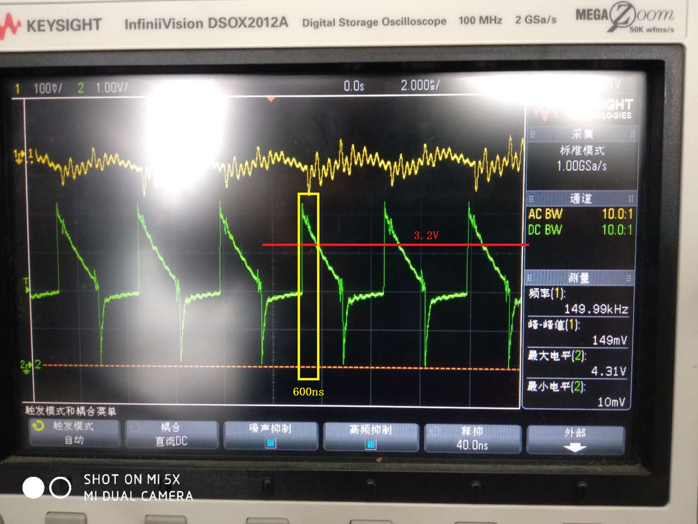
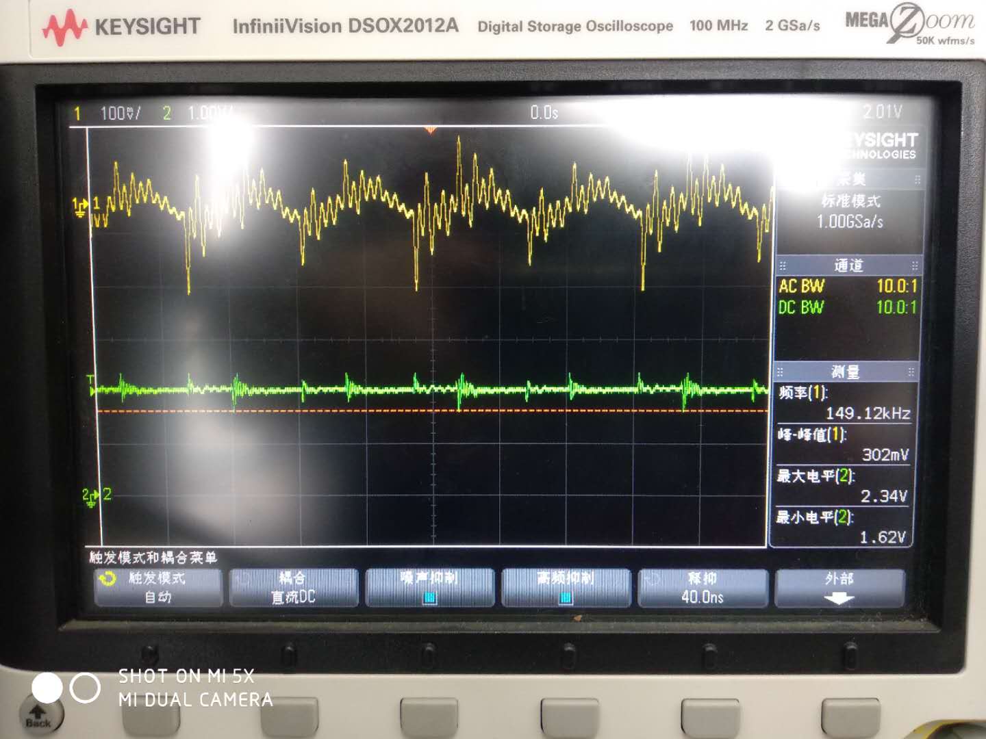
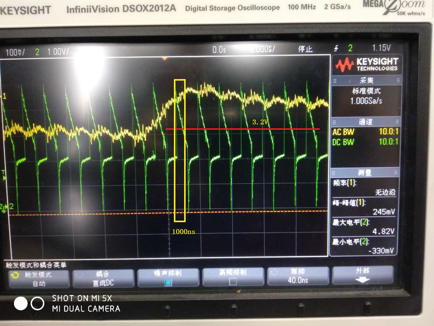
According to the manual recommendation, I connected a 100pF capacitor in series with the RT pin, and then injected a PWM wave with a magnitude of 0-3.3V and a duty cycle of 0.5 from 270kHz to 330kHz. According to the manual, the normal bias voltage of the RT pin is 2V, and the injected synchronous frequency is higher than 3.2V. However, after such PWM injection, the power supply is unstable, the output ripple will self-excitation to 200mV, the normal ripple is 50mV, and the frequency is 300kHz. Later, I adjusted the amplitude to -0.3V~2.6V and found that the power supply can be synchronized and stable.

There is doubt now. The manual recommends that the external synchronization frequency be 10% higher than the power frequency, that is, 330kHz, but the injection frequency is also 270kHz~330kHz. Why?

The manual recommends a high level greater than 3.2V, and I will be self-excited when I inject 3.3V, but it is normal to inject 2.6V. Why is this?

  • Hi zoujiangyilang,

    First, In you words, the operating frequency is 300KHz, if it is, then oscillator frequency should be 600Khz.

    Please confirm that the synchronous signal at RT pin is a PWM signal 10% higher than fosc and higher than 3.2V. May you attach the component connection circuit around RT Pin and RT Pin waveform?

    And you can try to reduce the synchronization pulse width at the RT pin from 0.5 duty cycle to 300-ns wide.

    Regards,
    Teng
  • Hi Teng,

    The oscillator frequency is 300kHz, HO and LO each switching at 150 kHz.

    The external synchronization frequency I injected into the RT pin is around 300kHz. Is this correct?

    Should not inject 150kHz external synchronization frequency, right?

    The recommended frequency of the injection is greater than 10% of the oscillation frequency. For example, the oscillation frequency of my power supply is 300kHz, so the synchronization frequency I injected is greater than 330kHz, right?

    Why must it be greater than 10% of the oscillation frequency? In fact, I injected an external synchronization frequency from 270kHz to 330kHz, and the power supply oscillation frequency can also be synchronized. Why is this?

    The high level in the manual is greater than 3.2V, which means that the voltage on the RT pin is greater than 3.2V, instead of the injected sync signal being greater than 3.2V, right?

    In fact, as shown below, I injected a 2.6V sync signal, and the maximum voltage on the RT pin reached 4.3V, which is also possible to achieve synchronization, right?

    In the above figure, yellow is the output ripple voltage, green is the voltage of the RT pin,

    and the injection sync signal is a 300 kHz, 0.5 duty cycle, high level 2.6V, low level -0.4V PWM wave.

    At this point, the voltage on the RT pin is greater than 3.2V for about 600ns, so that it is greater than 300ns, it can achieve the synchronization function, right?

  • In the above figure, yellow is the output ripple voltage, green is the voltage of the RT pin, and no sync signal is injected at this time. RT is around 2V and the ripple voltage is stable.

    In the above figure, yellow is the output ripple voltage, green is the voltage of the RT pin,

    and the injected synchronous signal frequency is 300kHz, the duty cycle is 0.5, the high level is 3.3V, and the low level is 0V.

    The maximum voltage on the RT pin reaches 4.8V, and the portion over 3.2V is about 1000ns long.

    At this time, the ripple voltage is unstable and there is self-oscillation.

  • In this case, why does it self-oscillate ?is the amplitude and duty cycle of the injected external synchronization frequency too large?
  • The width of the sync signal is reduced to 300ns, which means that the portion of the RT pin that is larger than 3.2V is longer than 300ns, right?
  • The external synchronization signal is sent to the LM5035 through a C21 (100pF) capacitor.

    Is this circuit connection correct?

  • Is there a requirement for the maximum value of the external synchronization signal injected into the RT?
    When I inject SYNC of 2.6V, the maximum value of the RT pin is 4.3V. When I inject 3.3VSYNC, the maximum value of the RT pin is 4.8V.
    Is the signal amplitude unstable due to excessive signal amplitude injected into the RT pin?
  • Hi zoujiangyilang,

    1. If the external clock frequency is less than the RT resistor programmed frequency, the LM5035 will ignore the synchronizing pulses. And the tolerance of the external resistor and the frequency tolerance is taken into account when determining the worst-case frequency range. So the external clock must be at least 10% higher than the free-running oscillator frequency set by the RT resistor. Here the external synchronization frequency should be greater than 330kHz.
    2. Yes, the voltage on the RT pin is greater than 3.2V, not the external clock signal. When the synchronizing pulse transitions low-to-high (rising edge), the voltage at the RT pin must be driven to exceed 3.2 V from its nominal 2-V DC level.
    3. The circuit is correct.
    4. Maybe 0.5 duty cycle is too large. I suggest to use a a narrow pulse as an external clock by applying to the RT pin. For example, the external synchronous signal frequency is 330kHz, the positive width is 300ns.

    Regards,
    Teng

  • Thank you for your advice and it solved a lot of my doubts.
    Is there a maximum limit on the RT pin voltage?
  • Hi zoujiangyiliang,
    Absolute Maximum Ratings of RT Pin is -0.3V~7V, which can be found in the datasheet. Thanks