This thread has been locked.

If you have a related question, please click the "Ask a related question" button in the top right corner. The newly created question will be automatically linked to this question.

TPS65218: How to identify Good and Bad TPS65218B1 on assembly board

Part Number: TPS65218

Hello TI

We have assembled around 400 units using TPS65218B1 series PMIC

almost 300+ boards work fine with no problem at all,

On all board, we have the same PMIC TPS65218B1 series 

Few PMIC does not work as desired and we measured the temperature around PMIC is 20-25 deg.

Few PMIC board works fine even at 50- 65 Deg.

Now we would like to measure some checkpoints on PMIC, please suggest how to and what to check so that we can identify the bad/abnormal PMIC vs Good PMIC.

We have both PMIC boards (Good and BAD PMIC) but unable to find differences or unable to figure out bad points in bad PMIC, 

Our end customer is asking to tell us waveform or impedance or other points in BAD PMIC which is different from Good PMIC. 

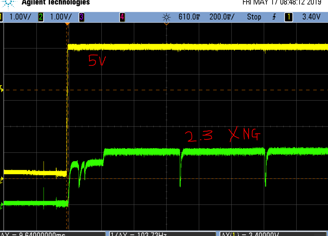
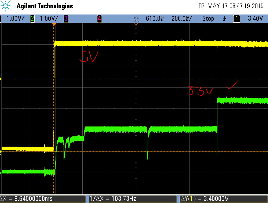
IN below image Yellow color is VIN_DCDC4 and Green color is output which is Zero 

1,2,3 Column we are getting 3.3V output but the last column (4th)  is NG means failed, PMIC failed to output 3.3V

IN below

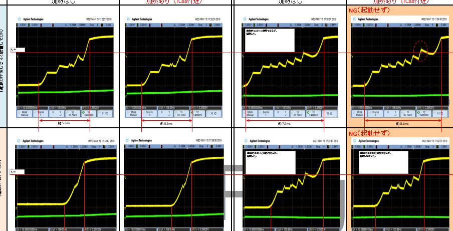
please suggest any clue or checkpoint by which we can figure out the differences 

Please reply to my every point mentioned above 

Thank you in advance 

  • Santosh,

    We have posted the Revision History from TPS65218 -B1 device to TPS65218D0 device in another e2e thread here: e2e.ti.com/.../747022

    I do not understand your explanation of the scope shots and cannot advise on them with more info.

    How is Yellow line VIN_DCDC4?
    What is the difference between top row and bottom row of images.

    It is not clear to me what I am looking at, so I cannot advise.

    When DCDC4 fails to startup, it will cause the entire system to reset. What other information is required?
  • IN above image

    VIN DCDC 4 is 5V which is captured below

    pls. find updated waveform.

    1. image - waveform - 3.3 V Output failed to start

    2. image 3.3 V OK

    IN our testing we observed that same PMIC initially start properly but after 1-2 hours fails, NO 3.3V output.

    In another board PMIC after temp rise by 30 deg. then fails initially start and works

  • Hello All
    Kindly update on latest post
    Some concrete clue by which we can easily identify bad vs good PMIC by physical or electrical characteristics
  • Santosh,

    I'm sorry, but if these measurements are accurate for the time it takes DCDC4 to turn on in the "Pass" case, then it my belief that neither of these scope shots show DCDC4 are working correctly.

    DCDC4 should approximate a monotonic increase from 0 to 3.3V, and it should only take a few ms for DCDC4 to reach the setpoint of 3.3V

    The entire power-up sequence should only take approximately 50ms, as shown in the scope capture below that I have just recorded in my lab.

  • To me, it does not make sense that DCDC4 can initially rise to ~1.6V, then rise to ~2.1V, then at a much later time finally rise to 3.3V and this is not causing any problems in the system.

    The VPG "time-out" specification is defined as "Occurs at enable of DCDC4 and after DCDC4 register write (register 0x19)" with a typical value of 5ms. If it takes longer than 5ms for DCDC4 to reach 3.3V, I would expect the system to power-down and try to re-start.

    In order to understand what is happening in your system, I would need more than just VIN (5V) and DCDC4 monitored on the scope. For example, when goes the PGOOD signal go high? When do DCDC1 and DCDC2 go high? All these timings are relative and dependent on the previous step in the power-up sequence.
  • Thanks for updates,

    Well, workaround solution for this issue is connecting 200pF cap between L4A and GND and start PMIC.

    It works fine, we have connected 200pF cap on a few boards.

    We have installed all the units at the customer location.

    But the customer is asking the guaranty of the solution, some assurance

    Kindly reply to following questions raised by the end customer

    The customer asked us two things.

    1) Confirm that there’s no bad influence when we add this capacitor to normal PMIC.

    2) Confirm that this problem will not happen again 10 years after.
    i.e. Are there any factor changing as time passed?

    Kindly reply asap.
  • Santosh,

    We cannot guarantee that the system will continue to operate for a specific number of years. The legal disclaimer on the bottom of every e2e page provides a link to the Terms of Use, and section 10. Warranties and Disclaimers which ensures that TI is not liable for any claims made on the site.

    Whether or not this system continues to operate for 10+ years depends on other factors outside of the PMIC, such as the inductor itself, the 200pF capacitor, the load on DCDC4, etc.

    The best thing you can do is thoroughly test the workaround in your system through characterization across temperature and using a large enough sample size to be statistically significant, using boards that were previously failing and boards that were previously powering on correctly.

    My personal stance on the matter depends on when the design was started, and whether or not the TPS65218D0 was available before the design went to production. The TPS65218 -B1 was changed to NRND status over a year ago, and the TPS65218D0 was available in November 2017. If the TPS65218D0 can be used in a design, then it should be used to replace the -B1 version. This way, no workarounds are necessary.

    However, the answer to your questions are as follows:
    1) Confirm that there’s no bad influence when we add this capacitor to normal PMIC.
    Answer: None of these TPS65218 -B1 PMICs are acting normally, and you can see this by comparing your "failed" and "OK" scope shots to the scope shot I shared. As a result, the workaround will improve the performance for all PMICs by adding a capacitor that removes some of the AC component of the DCDC4 regulator during start-up (DCDC4 is a buck-boost with a more complex internal circuit than DCDC1-3).

    2) Are there any factor changing as time passed?
    Answer: The issues with the TPS65218 -B1 PMIC are inherent flaws in the original analog circuit design. They are not time dependent or based on the aging of the PMIC. The issue with DCDC4 start-up that you are experiencing is primarily due to a lack of soft-start on the regulator during power-on, which results in a large inrush current. For the PMIC, this does not worsen with the aging of the device. But due to the effects of aging on the capacitor, the inductor, and the load the effectiveness of the capacitor may change over time.

    The workaround options are stated in this other e2e thread: e2e.ti.com/.../631514
    "Our recommended work around is to either place a shottky diode or a 100pf-300pF capacitor from ground to the L4A pin. A better ground connection to the DCDC4 output cap with multiple vias connecting to the powerpad, and putting the output cap close to the PMIC on the same side of the board can also help."
    You are welcome to evaluate the alternate workaround, "Place schottky diode from GND to L4A" and compare the results vs. the 200pF capacitor, and determine which solution is best for your system.