A related question is a question created from another question. When the related question is created, it will be automatically linked to the original question.
If you have a related question, please click the "Ask a related question" button in the top right corner. The newly created question will be automatically linked to this question.
TPS53679: Multiphase regulator_ can phase volatges overlap?
Thanks for the response. Let me explain more here..
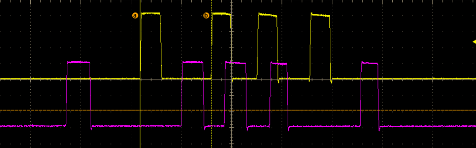
1.Can these signals overlap?
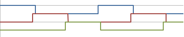
In TPS53679, phase overlap is allowed and it depends on VIN/VOUT/FSW/Number of phases to achieve higher duty cycle applications.
For example, if 5VIN/1.8VOUT/400kHz/3phase is the case, then overlap between phases will be overserved like this and in well-ordered.
However, the waveform you attached is not the good order compared with above, what is the VIN/VOUT/FSW/Number of phases in your cases?
2.what could be possible reason for overlapping?
Not well-ordered overlapping might be related to insufficient ramp amplitude, current/voltage sense loop is affected by noise, or improper compensator settings..etc, change ramp amplitude to the higher one will solve the issue in most cases.
During steady state operation, as long as no two consecutive PWM pulses within 1 duty cycle is observed, and ripple, transient meet the design requirement, it should be no issue.