


Other Parts Discussed in Thread: INA138, TINA-TI, INA213, INA193, INA214
I need to convert the TPS63020 into a constant-current source. The reason for choosing the TPS63020 is that it is the only part I can find on Digikey or Mouser that is suitable for out application due to input voltage requirements and output voltage/current demands. The way I want to do this conversion is to use a small sense resistor in series with the load and use the voltage generated across it as input to the INA138 current sense amplifier. The INA138 has a transconductance of 200uA/V. The output current from the INA138 can be used to generate the feedback voltage into the FB pin of the TPS63020.
I simulate the above condition in TINA-TI, and to the first order, it appears to work well. A VCCS set to transconductance = 200uA/V is used to model the INA138 output; this output current is converted to a feedback voltage via the 50k resistor. With a 50m sense resistor, the TPS63020 will raise its output voltage to push exactly 1A of current through the load. The load is just 2 LEDs in series here for the simulation purposes:
( The TPS63020 transient model was taken from TI's SpiceRack, fyi )
However on my physical TPS63020 circuit, on the actual PCB, with the exact same circuit except the VCCS is replaced by the INA138, I see the output voltage output varies wildly. The input current also varies wildly, and when I probe the switch node I am seeing erratic behavior on duty cycle and even switching levels. This I do not understand. Some scope captures below (Yellow is switch node: Green is output voltage) :

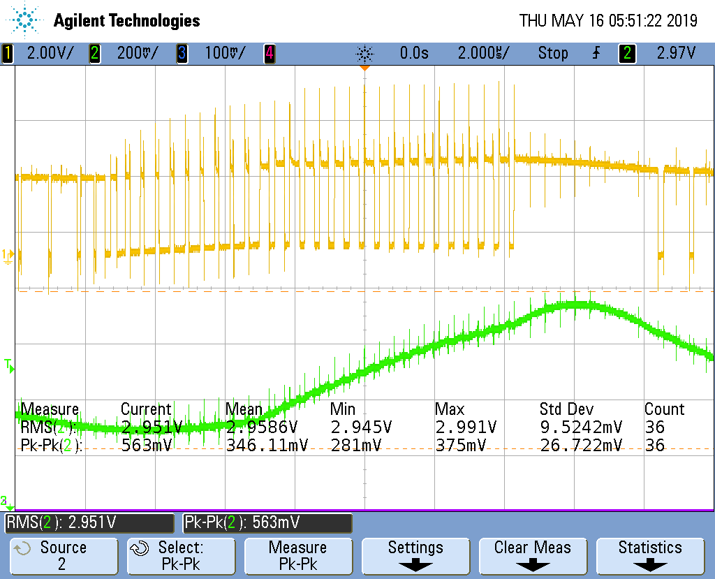

Can anybody from TI comment on what I am seeing when I probe these waveforms? Why does it seem the TPS63020 cannot regulate in this configuration?
What can I do to adapt the TPS63020 to a constant-current source using the INA138 as my current-sense amplifier? Could this be a control loop problem? Is there a way to modify the control loop in the absence of an external compensation pin?
Thanks in advance for reading.


