This thread has been locked.

If you have a related question, please click the "Ask a related question" button in the top right corner. The newly created question will be automatically linked to this question.

BQ76940: leakage current when CHG and DSG off

Part Number: BQ76940

Dear experts,

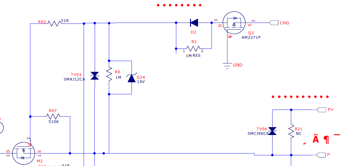
Our customer noticed that there is a problem in our low side CHG and DSG driver project . The attached file is our schematic, we followed the connection in bq76940 datasheet. And we also noticed some reference design adds a 1k resistor R4 between CHG pin and CHG mos gate (as below), I wonder what the effect of this 1k ohm resistor is and can this resistor be ignored (now the customer sets R4 0 ohm).

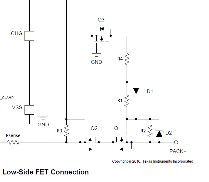
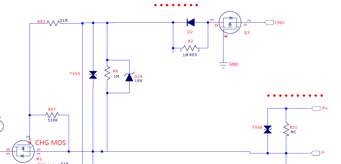
Our problem is when CHG and DSG mos off, the pack still has voltage on it when we measure it with multimeter. And some end customers thought it's dangerous. After testing, customer found there is leakage current on the line between CHG pin and CHG mos gate, about 20-30uA. When customer disconnected this line by taking off 0 ohm R4, the voltage disappeared.

Could you help us to solve the problem and tell me the effect of R4 resistor? Thanks a lot.

  • Hi Minqi,

    This circuit is discussed in detail in the FET Drive section of the BQ769x0 Top Design Considerations app note: www.ti.com/.../slua749a.pdf

    R4 and R2 for a resistor divider where R4 is typically around 1k and R4 is typically 1M. I think the customer schematic might be increasing the leakage current since the configuration is slightly different and there is a second resistor in parallel in the case where both FETs are off.

    Best regards,
    Matt
  • Hi Matt,
    Thanks for your answer, but I still have some confusion. I read the last paragraph in page 11 of this app note and my understanding is that CHG sink current referred in this paragraph is the leakage current in my customer's case. So in every case when CHG and DSG FETs off and a load is applied to the battery, there always exists leakage current between CHG pin and PACK-, am I understanding it correctly and did you find similar situation during your test? And we can set R1 larger to reduce the leakage current, or is there any other method to solve the problem? Thanks for your reply.
  • Hi Minqi,

    Internally the CHG pin uses a high impedance pull-down when disabled, so there will be some leakage current. Increasing R1 reduces the leakage current.

    Best regards,
    Matt