This thread has been locked.

If you have a related question, please click the "Ask a related question" button in the top right corner. The newly created question will be automatically linked to this question.

BQ25703A: No charging current

Part Number: BQ25703A
Other Parts Discussed in Thread: BQ25703, BQ25730

Hello

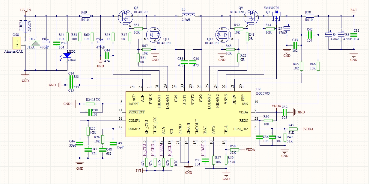
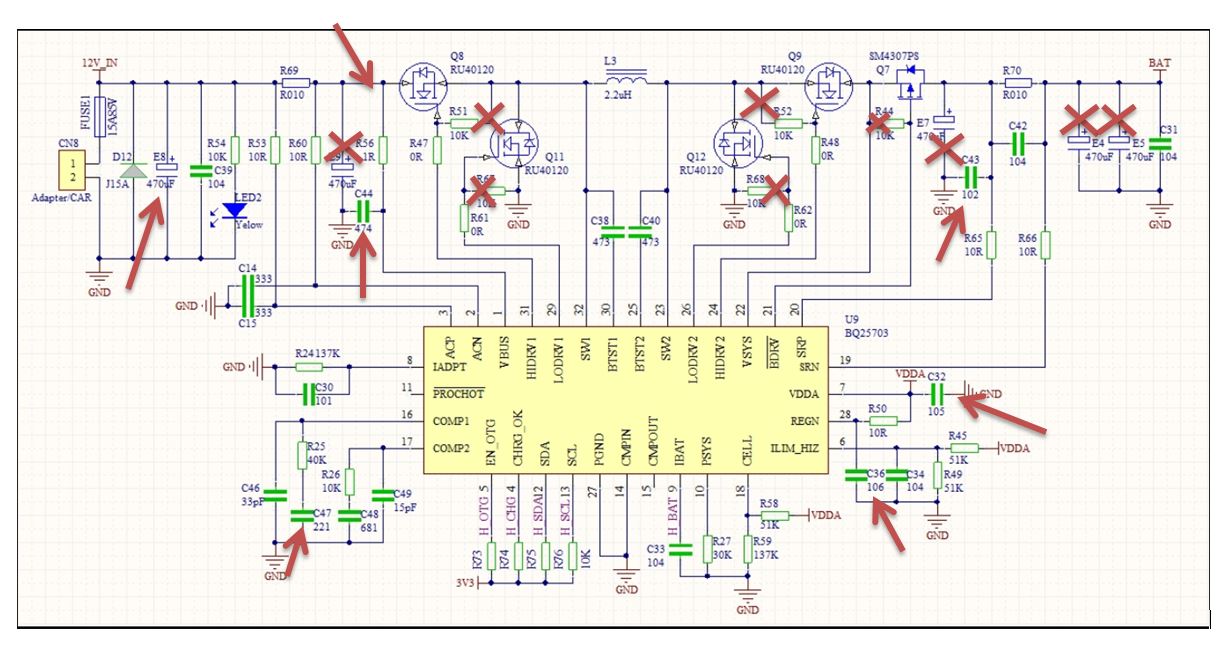
We have some problems with BQ25703, We use it to design a 4-series lithium battery charger, here is the schematic. Input power supply  volatge is 17V, battery volatge is 14V

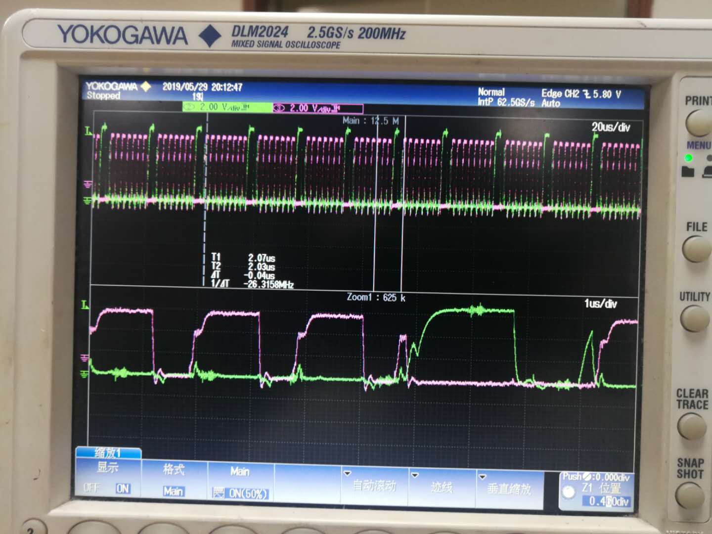
Now we can read '' fast Charging'' from I2C, but the actual current is 0, pls help us find the problems.

  • Hey BO,

    After looking at your schematic, I would ask you to check the BQ25703AEVM for a reference for the correct schematic/design implementation.

    You will notice that your caps are not in the correct locations, you have several 10k pull-downs on your power stage FETs, and decoupling caps that are way too large.

    The charger may be having stability issues due to this or poor regulation/feedback.


    Regards,
    Joel H
  • Hi Joel:

    After comparison checking with BQ25703EVM, I have already removed the 10K pull-downs and corrected decoupling caps.thank you so much!
    While repeatedly checking there, still I wasn't aware which caps in the wrong location ,could you kindly point it out on my drawing ?
    Highly appreciated!

    Best Regards,
    Bo
  • Hey Bo,

    The electrolytic capacitor E9 should not be there.

    I would also recommend adding much more ceramic capacitance on both the input and output (VSYS). As seen on the EVM, we have about 60uF on both the input and the output. Additionally, from the EVM schematic, you will notice that there is no E9 large electrolytic capacitor placed between the RAC and first HSFET.


    Regards,
    Joel H
  • Hi Joel:

    I already noticed that improper  location for capacitor E9 ,we was considering lower cost by using electrolytic capacitor earlier and will change to ceramic capacitors as your suggested from now on, thanks!  While we are thinking that all those capacitor applying issue should not effect the basic function for BQ25730 ?

    Big problem for us is that totally no charge current at the moment, and we had tried to close the input management then charge current showing up, while the BQ25703 is heating too much and the wave graphic we had measured just as attached,  pls kindly help to have a look .

    Thank you!

    Best Regards,

    Bo

  • Hey Bo,

    That capacitor placement is critical. If it is placed in that location, it will affect the converter's ability to regulate. Changing to ceramics is not sufficient; it must be removed so as to not impact the feedback and control of the converter. 

    Regards,

    Joel H

  • Hi Joel:

    Sorry I still need your help, we have removed the capacitor E9, but still no charging current, do you have any idea about other possibilities?

    Thank you so much!

    Best Regards,

    Bo

  • Hey Bo,

    I re-reviewed your schematic and there are several things incorrectly placed or improperly sized. 

    As I mentioned in a previous post, your schematic has many differences from the EVM schematic that are likely the cause of the charger not functioning correctly. In order to verify that, it will require some extensive changes to your current design. 

    Below I have attached a screenshot of most of what is different from the EVM schematic. 

    Critical items are the amount of ceramic capacitance required on the input, very high frequency capacitors needed between the input current sense resistor and the HSFET1, the placement of the output filtering capacitors on VSYS that are just not present in your schematic, the COMP1 capacitance needing to be 1.8nF, and the placement of various capacitors in the wrong locations and/or incorrectly sized such as E7, E4, E5, etc. 

      Lastly, I would also recommend you review the capacitance values in your schematic document. If C47 = 221 = 2.2nF, then it would stand to reason that C48 = 681 = 6.8nF and C38/40 = 473 = 473nF. There are not the correct values as seen on the EVM schematic.

    Regards,

    Joel H