This thread has been locked.

If you have a related question, please click the "Ask a related question" button in the top right corner. The newly created question will be automatically linked to this question.

TPS92515: PWM pin

Part Number: TPS92515

Hello,

I try the TPS92515HVEVM.

I make the dimming the power of the LED by the Iadj pin, at 0 to 0.5V (about 200 mA). this is OK.

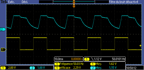
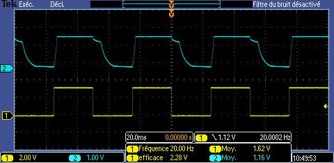
Also, I want use the PWM pin to blinking the LED at different frequency (at 50% of duty cycle). It's work fine to 1 to 5000 Hz, except between 70 and 100 Hz. In this frequency the output LED frequency is divided by 2 relative to the input frequency.

Have you an explain ?

Best regards. 

  • Hello Delmas,

    I'm not sure what you are doing. The input voltage source should be a DC source, what is the "input frequency"? Is this the PWM command to the EVM? If so can you look at PWM at the IC and the output voltage and current for the LEDs with an oscilloscope?

    Best Regards,
  • Hello,

    Yes the input voltage is DC source at 24V.

    The input frequency is the PWM command to the EVM. 

    Yes I see with an oscilloscope, the frequency of the input and the output (on the LED side) is the same between 1 to 5000 Hz, except when the input frequency is between 70 to 100 Hz.

    Here, the output frequency (on the LED) is divided by 2 (when I have 80 Hz in input, the LED are at 40 Hz).

    Best regards

  • Hello Delmas,

    What is the output voltage? Can you provide oscilloscope pictures showing this, along with Vin, Vled, Vcc, PWM? Work correct and not correct? What is your switching frequency?

    " If so can you look at PWM at the IC and the output voltage and current for the LEDs with an oscilloscope?"

    Best Regards,
  • Hello Delmas,

    I haven’t heard back from you, I’m assuming you were able to resolve your issue.
    If not, just post a reply below (or create a new thread if the thread has locked due to time-out)

    Best Regards,
  • Hello,

    No, I don't resolve the problem. I send you oscillo picture. 

    The input voltage is 24Vdc. I have 0.1 V on the Iadj pin, and I have a frequency input on the PMW pin (between 0 and 3.3V), is the channel 1 (yellow)

    The channel 2 (blue) is the LED+ pin.

    So as you see, the frequency 20, 50, 110 and 1000 Hz are OK and at the frequency 80Hz (is the same between 70 and 100 Hz) the output is not the same as the input frequency.

    Have you an idea ?

    Best regards

  • Hello Delmas,

    What is your Vled/Vout? According to the oscilloscope pictures it's just over 1.5V. Notice on your 50 Hz picture it is not operating correct either. When told to turn on it doesn't right away. I'm guessing either Vboot or possibly Coff if your load voltage is very low. Can you get a picture of Vboot along with the SW node (so I can l see the boot voltage, it's the different of the two). Also I'd like to see the Coff pin.

    You can try increasing the boot capacitor value, say double, to see if it changes behavior.

    I'll probably be asking for a lot more information of your design, such as Roff, Coff, Vin, Vout, oscilloscope pictures of the output current at different operating points, etc.

    Best Regards,
  • Hello Delmas,

    I haven’t heard back from you, I’m assuming you were able to resolve your issue.
    If not, just post a reply below (or create a new thread if the thread has locked due to time-out)

    Best Regards,

  • Hello,

    I try to increase Cboot to 0.3 µF and it solve my problem.
    I have to design my custom board, and I come back if I have other problem when I debug it.

    Best regards