This thread has been locked.

If you have a related question, please click the "Ask a related question" button in the top right corner. The newly created question will be automatically linked to this question.

TPS65217: TPS65217. SYS pins floating

Part Number: TPS65217

Hello,

I have inherited a project since a team member left the company. I have just received the boards that were designed and noticed that the PMIC is not outputing any voltages. and the current consumption is 0.01A (apparently the PMIC is trying to do something but isn't able to).

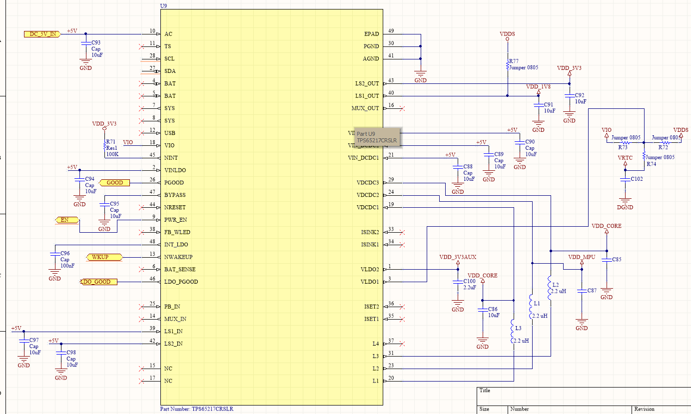
After a review of the datasheet and the schematics this is what I noticed ... the SYS pins were left floating. According to the datasheet there are many pins that say "This pin must be connected to the SYS pin", so it's safe to assume that he made a mistake.

The thing is that I distinctly remember that the original person to design the board (another coleague who left) connected the sys pins together with the input 5V (the 5V that goes into AC pin) and of course the board didn't work properly, but I distinctly remember that in order to fix this and make the board work I took a box cutter and cut the connection between the sys pins and the 5 V input, isolating the SYS pins from the rest of the ciurcuit, just connecting them to each other and the board came to life (all those pins that require the 5 V were connected directly to the 5 V input).

I tried measuring one of its outputs (oin 20 connected to an inductor) and noticed that it tried to do something, it went up´to ~250 mV before going back to 0 V. This tells me that the PMIC is not dead, but there is something wrong.

Unfortunately this is not my project, I didn't design it, I was a member of the embedded software team, but now the hardware and embedded software teams are only 1 and now I have hardware responsabilities from designs that I didn't review nor designed. It seems that I have already answered my question ... that I probably need to cut up this board and do some wire ups to get it working, but i really need a second opinion before I start cutting anything.

If I go by my previous cut that isolated SYS pins from the rest of the circuit but left them connected to each other, then all I need to do is short those pins. But something tells me that I'm gonna have to cut many pins and wire everything up to get it working. Any advice?

  • Ok. Update time.

    They made 2 boards. I tested the other board and it was actually outputing 1.8 V, it was actually draining an expected amount of current (~0.1 A) .... but it suddenly stopped working and it started draining 0 A. I really have no idea as how to proceed now. I need the board to be energized before I can port linux to it. Any ideas on how to debug the PMIC?
  • Pablo,

    It would be helpful if you can share the schematic of this design, but the correct wiring of this device is shown on page 74 of the TPS65217 datasheet in Figure 60.

    A correct alternate wiring for when AC<=5V and there is no battery in the system (which would normally connect to BAT pins) is shown in Figure 62 on page 77.

    Either the main supply must connect to AC pin, and SYS pin connected to inputs of the voltage regulators (VIN_DCDCx, VIN_LDO, etc.) or the main supply (VIN<=5V) connects directly to BAT pin and the inputs to all the voltage regulators (while SYS pin must be terminated with a 4.7uF output capacitor).
  • Not sure which pin is coming up to 1.8V (SYS or VDCDC1). If you are using the TPS65217A or TPS65217B version of the device, DCDC1 will output 1.8V

    If VDCDC1 is coming up to 1.8V then turning off, it means another voltage regulator in the system has encountered a fault condition and the device shutdown instead of finishing the power sequence. In this case, you would need to check all the other voltage regulators in the system to see which one is failing.

    If SYS is coming up to ~1.8V, then you need to check to see if the PWR_EN pin is being set high.
  • Here is the schematic provided to me. It seems .. strange. Also I was measuring 1.8V on R73 ... which are pins 18 and 3 (VIO and VLDO1). Unfortunately I couldn't get to measure the other voltages.

  • I'm gonna try to measure the SYS pins ... it's gonna be a little hard since the pins aren't connected to anything.

    After that I'll get back to you with what I was able to measure.
  • Pablo,

    Based on the schematic, I would say trying to re-wire the +5V input from the AC pin to the BAT pins is your best bet, but there are a lot of issues that need to be addressed here.

    Even if you are able to cut the trace that connects +5V to AC and re-route the power to the BAT pins, you will at least need to do the following:
    1) Pull BAT_SENSE to GND through a 10k resistor.
    2) Connect a 4.7uF capacitor from SYS pins to GND.
    3) Solder a wire onto the PB_IN pin to be able to toggle it Hi-Lo-Hi to simulate a push-button press. In the final design, you would either need a physical push-button or to short PGOOD to PB_IN. Powering the PMIC from BAT instead of AC means you need a push-button press as a wake-up event.


    You can try to just do item #2. The system would power on, but I don't think the system will work very well over time. In other words, it may reset unexpectedly or get stuck during a power-cycle.

    There may be some other issues here that I am not aware of, but right now I just want the system to turn on and stay on for a few minutes.
  • Hi[ and trhank uyofor your help.

    PB_IN is something that I don't like to rely on. I can't deppend on a button press to get this product to start working. A simple power on must be enough. So I see that I'll probably have to rewire a few thing for the next version to get it working.

    I just came back from the weekend and I haven't been able to measure anything. I'll get on it today and then I'll get back to you

  • If the +5V supply is routed directly to BAT pins, then shorting PGOOD to PB_IN should be sufficient to simulate a push-button press, as I mentioned in my previous reply.
  • Ok. Let me give you an update.

    1 - I left everything as is and just connected the 4.7uF cap to the SYS pins and measured with an oscilloscope the sys pins. It apparently tried to do something .. it went up to 4 V then tamped doen to 1 V and kept doing it. As you predicted it got stuck in a power cycle. I didn't rewire to BAT just to see what would happen ... now we know
    2 -  I tried cutting the AC pin and feeding the BAT pins. Unfortunately it's very difficult doing this work, and other things in parallel, when I don't have the proper equipment so it'll take me some time to update on this..probably tomorrow
    3 - There is another board with an already soldered eMMC on it. On this board it doesn't work. The eMMC starts heating up a little bit and the SYS pins are stuck at ~300 mV ... it doesn't do the power sequencing like the other board.

  • Ok. I got it to work temporarily. I was able to measure all the correct output voltages, but it has stopped working.

    I did everything on your list, except for the 10k resistor to GND for pin BAT_SENSE. Recentky it has stopped working, but the following is happening.

    - There is 5V in BAT pins (4 and 5).
    - SYS pins and BAT pins are not shorted and when I turn on the power supply i get 5V on SYS pins, stragenly the exact same voltage as the input voltage for BAT pins.
    - No more voltages
    - PGOOD, which was connected to PB_IN (25 and 26) are shorted and low.