Because of the holidays, TI E2E™ design support forum responses will be delayed from Dec. 25 through Jan. 2. Thank you for your patience.

This thread has been locked.

If you have a related question, please click the "Ask a related question" button in the top right corner. The newly created question will be automatically linked to this question.

UCC23513: UCC23513

Part Number: UCC23513

Hi,

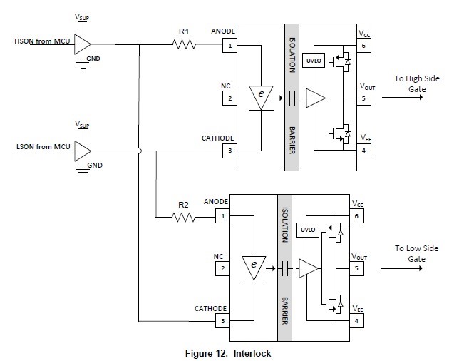
In UCC23513 datasheet, a suggestion interlock circuit is proposed. But I am curious about the CMR problem especially when LED is off. Always we shunt a transistor with LED when LED is off which is good for CMR. But for the Interlock circuit, there is no shunt path for LED off. Will I face the CMR problem with interlock circuit?

  • Hi Dragon,

    Thanks for your interest in our driver, my name is Mamadou Diallo, I am AE supporting the High Power Drivers team.

    If i understand your concern correctly, it sounds like you're concerned with potential impedance mismatch from the connections that could allow transients coupling from the Anode to Cathode when the e-diode is off. Please confirm if I am wrong.

    The interlock function is actively driving both anode and cathodes where the output stages of the buffers shown on the diagram represent or can be modeled as transistors which effectively eliminates the use of any external transistors.

    If you want to account for any CMR from impedance mismatch or imbalnce, you may insert equal value resistors to allow for impedance balance between anode and cathode and equalize common-mode voltage change between the 2 pins. I have attached a blog below from my colleague where this implementation would address concerns for your application.

    Alternatively, to save resistors components, you can move R1 and R2 on your picture as shown below to ensure proper impedance balance between the anode and cathode pins.

    Please let us know if you further questions or press the green button if this addressed your concerns.

    Regards,

    -Mamadou

  • Part Number: UCC23513

    Hi  Mamadou:

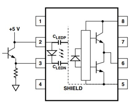
    Thanks for the response. My original circuit is as below. When the LED is off, due to coupling from the secondary, the path from +5V-->LED-->CLEDN is possible. But with a shunt transistor, the path transfer to +5V-->TRANSISTOR-->CLEDN. 

    So I am interested on : Can interlock circuit solve this issue?

  • Hi,

    Thanks for sharing your circuit.

    Interlocking the devices through matching buffers and matching external current-setting resistors will ensure that both outputs are never ON at the same time regardless of common-mode noise in the circuit.

    The shunt transistor is not required for multiple reasons here:
    1. With matching external resistors and identical buffers (or equal internal resistance of buffers and minimal p2p variation) to ensure equal and balanced forward currents at both ICs. This helps equalize common-mode transients on both anodes and cathodes(assuming a non-optimized layout)

    2. Because there will always be current flowing through the transistor (when LED on and off), this takes away from the IF current to required to turn-on the diode. It also increases the power dissipation in the system as the transistor will have current essentially causing unused power dissipation in the system.

    3. Because of the higher working isolation voltage capability and the higher common-mode transient immunity over traditional optocouplers, UCC23513 is better equipped to handle common-mode transients from the power stage.

    This configuration was evaluated on our 3-Phase Inverter Reference Design copied below:
    www.ti.com/.../tidueg8a.pdf

    Please let us know if you have further questions or press the green button if this addressed your inquiry.

    Regards,

    -Mamadou