Hi Team,
1. From datasheet Figure23., the Vp-p is about 0.2V, But it is 0.1V(+-2.5%) when I using Webench simulation.
What makes the difference? Which one I can refer to?
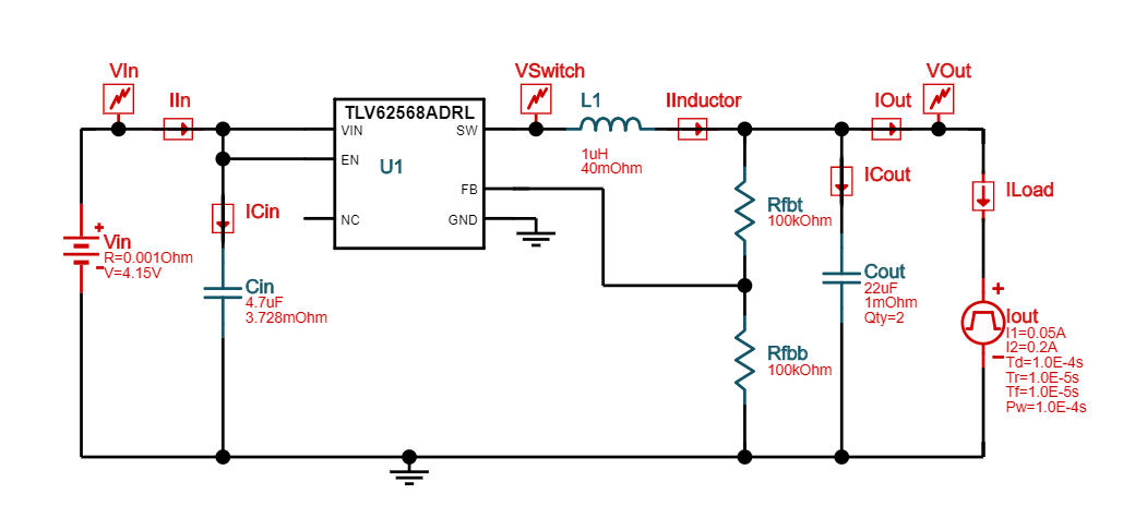
2. Now my application is 0A to 200mA, Vout is 1.2V within +/-5%, does TLV62568A could meet the spec?
Thank you,
C.T.