This thread has been locked.

If you have a related question, please click the "Ask a related question" button in the top right corner. The newly created question will be automatically linked to this question.

LM5160A: converter burns every time I power it up...

Part Number: LM5160A
Other Parts Discussed in Thread: LM5160, LM5160-Q1

Hi TI expers,

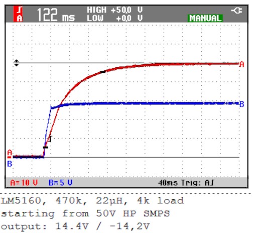
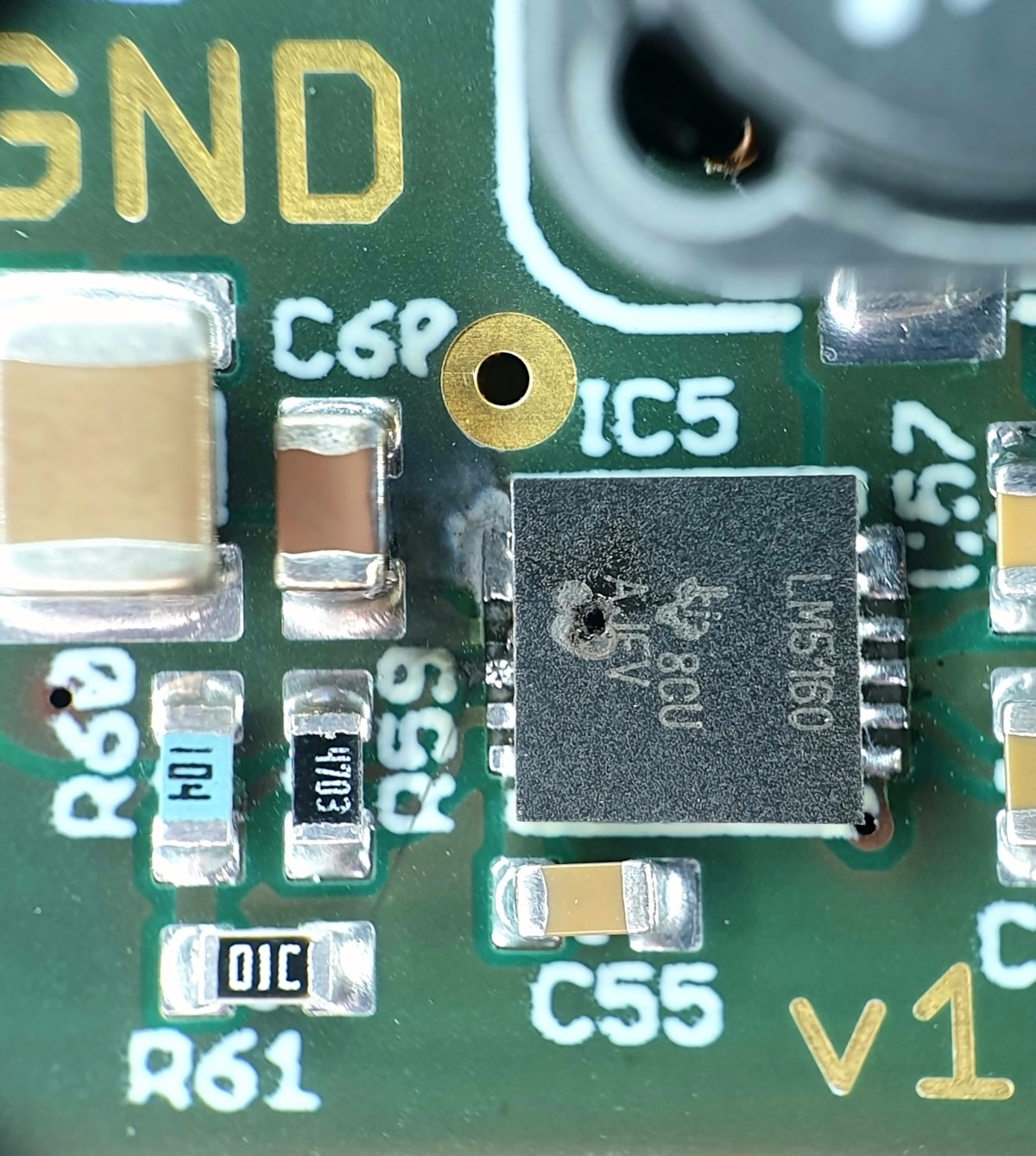
I designed small FlyBuck converter with LM5160A controller to generate a symmetrical supply rails from 50V DC source. I simulated the circuit and the simulation works well, but after creating small test-board I have hard time to get it run. Supplying the circuit from current limited bench power supply everything works well. Supplying the circuit from high power 50V power supply it burns directly :( Guys - what is here wrong??? Please see attached schematic and the photo showing where the IC burns - every time it burns exactly in this same point.

  • Hello Tomasz,

    Since the converter works when connected to your bench supply, it is likely that the large supply is overshooting when being connected or enabled. Have you tried slowly increasing the large supply?

    Regards, Robert
  • Hi Robert,

    Thanks for your replay. The high power converter has no enable so I just connecting the module to the power supply. It will be hard to imagine that 50V power supply is overshooting because it has quite big caps on the output (this is why it cannot be easily current limited...) The maximum voltage of the LM5160 is 65V and once it has happens even with 40V :(

    Tomasz
  • I guess the damage is somehow caused by over current. I use inductor with relatively small inductance - only 22µH... But according to calculation/simulation to current shall stay below saturation and below maximal current of the LM5160A switch. Is there during start-up any moment when the switch is opened for a longer time than defined COT? So the current can rise to high?

    and other idea???
  • Any other idea???

    Could someone take a look on the schematic because for the inverted voltage connection of the coupled inductor and GND is slightly different than standard application note from TI...

    The issue happens only starting from high voltage without current limit
  • Hello Tomasz

    While the large supply that you are using may not overshoot its voltage setting, when a circuit with ceramic capacitors is hot plugged into this supply, peak voltage as high as two times the voltage on the power supply may be reached. Very few circuits without input protection will survive this type of test. You can probe for peak voltage with an oscilloscope. Be sure to sense directly across the input capacitor closest to the IC. You can also try a large, 100 uF, electrolytic connected directly across this capacitor to reduce ringing during hot plug.

    During startup, pulses can be a longer but not so long that this should be a problem.

    What is the saturation rating for your inductor?

    Regards, Robert
  • Hi Rober,

    I checked with scope and cannot see any overshoot... I will try to make some more measurements and share with you.

    Any other idea why the circuit doesn't start properly? Is the circuit / schematic / design right?

  • Hello Tomaaz,

    As previously mentioned by Robert, It is likely overshooting at the input.  From the pic you have posted, it looks like electrical over stress at the input.  If you  hot plug the voltage or have a fast rise time of the input voltage, there will be a huge overshoot, particularly If you have long wires to the board. the way to mitigate this is to place a damping cap in parallel to existing input caps to dampen the over shoot caused by fast rise time, parasitic inductance of the input cables and low ESR input ceramics.  Suggest selecting an electrolytic of at least 47uF and an ESR>0.5ohm.  Place this at the input side where the wires connect to the board and retest.

    NOTE: the sat current of your coupled inductor must be rated to a level greater than the max peak current limit, which for this device is 2.875A.  This current can occur at start up due to rise time of vout and inrush currents.  

    I hope these suggestion help, feel free to reopen thread, if not?

  • Hi David.

    thanks for your replay. I made some more tests and in total destroyed 4 of my 4 test boards... but, I made some more measurements. The first I checked the input voltage and unfortunately I cannot see any overshoot on the input :( Please see the screen shot below:

    The voltage is not measured on the input but directly on the power supply. The board was connected to the power supply with 15-20cm cables.

    The test circuit was destroyed exactly where you can see the voltage drop on the screen shot :(

  • The inductor I used was Coilcraft MSD1260-223 2x 22µH with saturation current of 5A.

  • After some modification last board was working quite good and started without any additional capacitor on the input. I additionally loaded the output with 4k, 1k 500R resistor. See attached input and output voltage during the startup:

    Unfortunately after some time like 20min testing this board was also damaged. Once by start this same failure happens:

  • I would say there is no overshoot on the input and the inductor saturation current is rated way higher then maximal current of the LM5160... any other idea?

  • Hello Tomasz,

    If you depopulate D2 are you able to cause the device to fail?

    If removing D2 resolves the issue you can opt to leave depopulated, or I strongly suggest you either reduce the voltage on the primary to 12V and below, The VCC has an Abs max rating of 14V. 

    Supplying a voltage to VCC causes strong gate drive currents which in turn causes high DV.DT to be seen at the VSW node.  This in turn causes excessive voltages, due to ringing at Vsw node, which can exceed VDS rating of the internal Devices.

    Hope this helps?

    If not please feel free to reopen thread, thanks.

  • Hi David,

    Yes, indeed, this is what I also found, that the rating of VCC is 14V and my circuit gives slightly more than 14V. So first I depopulate the diode and I thought everything is good. I also adjusted the output voltage to 12.5V because 12.5V is actually the voltage I need - the circuit supplies TPA5532 amplifier. Unfortunately also this board failed after some time - it was the last one I had with LM5150A...

    I have one additional board wit LM5160-Q1 - different package and without the diode. The board works quite good and supplied since days my amplifier. I would say there is no differences between the boards with QFN and Q1 device and this is why I do not understand why this board works ok and all other boards are damaged :( Other difference is, the board with Q1 device gives slightly different voltage.

    Finally I changed the auxiliary supply of the amplifier to different topology but I will try to give a try to the circuit one more time because I like it - is really small and compact on the board. I have just to learn a bit more about COT regulation to better understand the operation. As soon I have some more time to play I order new test boards and try it again :)

    Thanks for your support! Take care, Tomasz

  • Hello Tomasz,

    The ringing as a result of stronger gate drive currents due to external VCC, is dependent on layout.  The layouts between the two boards are likely slightly different (even lead inductance between packages are different) and as a result can be the difference in robustness here?  

    In short I believe that reducing the VCC voltage further or removing the diode that feeds the VCC is the best option in your case.  If you do not need to use the external VCC I would remove, as mentioned I would supply 12V (and not 12.5V) to the anode of the diode that feeds VCC so that VCC voltage is ~11.5V. If this is not possible, I advise to place a 5ohm resistor in series with C4, this will slow the DV/DT and reduce ringing and provide more robustness for your design. 

    On a final note, I would not be supplying a VCC above the recommended 13V on VCC.  If you are even slightly above 14V (abs ax rating) you run a likely risk of damaging the device.

    Hope this helps?