Other Parts Discussed in Thread: TLVH431
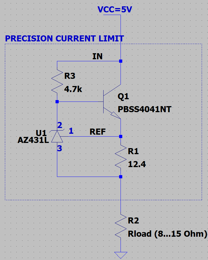
I am currently working on a circuit involving a current limit circuit (100mA) based on an 431 voltage reference variation from Diodes Inc. (AZ431L). It works fine. We wanted to replace this voltage reference with a LM4051-N from Texas instruments, as the datasheet indicates this is better in terms of accuracy.
However, for some reason, it does not work. It does not work in practice and it does not work in simulation (we only looked at a simulation after we noticed it does not work in practice, expectation was that we just replace the reference and it works). Of course, we also changed the value of the R2 resistor from 12.4Ohm to 12.1Ohm (as the Vref of the two parts is slightly different). "Does not work" means the load current is about 140mA instead of 100mA and both practice and simulation indicate this value to be quite dependent on the R3 biasing resistor (which it should not, considering a sufficiently low value for that resistor is selected).
As nomenclature regarding Anode-Cathode is a bit blurry in the datasheets of the two components, we had some doubts at one point that these two components might not be pin-to-pin matching, but we eventually decided they are. A second look might not hurt.
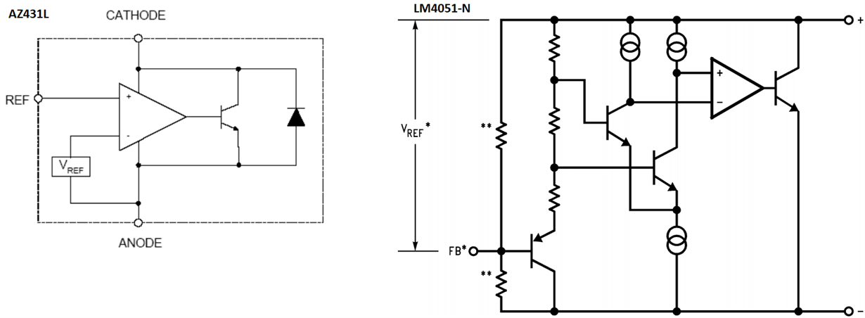
I fail to understand why the TI part does not work. The block diagram of the two components indicate that in the Diodes Inc. part the REF input goes to the non-inverting input of the opamp inside the part, whereas the more detailed block diagram of the TI part indicates the same input (called FB in the TI datasheet) somehow influences both the inverting and non-inverting inputs of the opamp. Of course, these are just functional diagrams, I do not really know if in the end the parts are similar or not inside.
The fact that TI has some TLVH431 makes me wonder, as it looks that this is a more exact corresponding part of the current Diodes Inc. part we are using. Unfortunately that is equal in performance to the existing part, so no gain changing it.
So to sum up the question: why does the TI LM4051-N not work in the same circuit?
Best regards,
Cristian


