This thread has been locked.

If you have a related question, please click the "Ask a related question" button in the top right corner. The newly created question will be automatically linked to this question.

LM5109B: LM5109BMA/NOPB : Please verify schematic

Part Number: LM5109B
Other Parts Discussed in Thread: UCC21220

Hi,

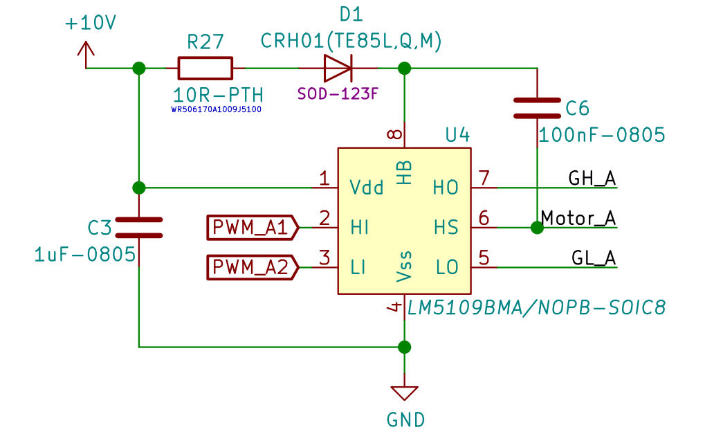
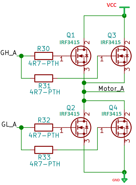
We are using LM5109BMA/NOPB for BLDC motor driving application. The Motor is 60V/5A rated.

We are using three LM5109BMA/NOPB chips to drive three half bridges.

We are facing high side output not coming from the Chip. Many times LM5109BMA/NOPB gets damaged.

Request you to verify the attached circuit and provide your valuable comments for same.

  • Hi,

    Thanks for your interest in LM5109B. I work on the applications team in the high power drivers group and can help you with your question.

    Your schematic doesn’t have any obvious faults. I would recommend placing filters on HI and LI to prevent noise from corrupting your input signals. This can be a straightforward 100-pF and 100 Ohm low pass filter.

    I have a couple questions:

    Why are you using paralleled MOSFETs? IRF3415 can handle 30A continuous, and your motor is only rated for 5A.

    Do you have any scope shots of your circuit while it’s operating? I can’t really determine likely cause of malfunction without seeing the gate drive inputs and outputs.

    What is the switching frequency? If the high side is turned on for too long, Cboot will discharge and our driver will drop below UVLO falling threshold and turn off.

    Feel free to share your layout as well. Motor drives are particularly sensitive to layout issues, and I’m glad to help point out improvements which could be made to improve performance.

    If this helped answer your question, could you please press the green button? If not, feel free to continue asking questions.

    Thanks and best regards,

    John

  • Hi John,

    Thank you for your kind and quick response..!!!

    As per your suggestion I will place filter on HI and LI.

    I was referring your "Automotive 48V 1kW Motor Drive Design" given on below link :

    www.ti.com/.../tidrin2.pdf

    If you notice the mosfet used is having a rating of 197A even though motor is rated at 1KW/48V [20A].
    It would be good if you can let me know about how you calculate the mosfet rating for motor.

    I don't have the screenshots but I can get them shortly.

    Our max switching frequency is 20Khz.

    Attached is the full schematic and layout done in Kicad.

    Thanks..!!!BLDC Design.zip

  • Hi Alex,

    Thanks for providing the design you're referencing.

    I think they used these MOSFETs for their low Rdson, which will significantly reduce conduction losses, allowing the designer to not use a heatsink.  If you properly heatsink your TO-220 FETs, there shouldn't be a need to parallel them to reach 5Arms operating current.

    Take a look at these blog posts to learn more about thermal design in motor drive systems:

    https://e2e.ti.com/blogs_/b/motordrivecontrol/archive/2015/03/27/optimized-thermal-design-for-three-phase-motor-drives-in-power-tools-part-1

    https://e2e.ti.com/blogs_/b/motordrivecontrol/archive/2015/04/22/optimized-thermal-design-for-three-phase-motor-drives-in-power-tools-part-2

    I'll try to get back to you on Monday about the schematic/layout.

    Thanks,

    John

  • Hi Alex,

    Are these your most recent files? It appears that the half bridges are driven by an IR part and the surrounding circuitry does not match what you had attached earlier. Please understand that I can't comment on the application of our competitor's part.

    I also can't open KiCad layout files. I recommend reading through this application report and following the best practices within.

    http://www.ti.com/lit/an/slva959a/slva959a.pdf

    If this helped answer your question, could you please press the green button? If not, feel free to follow up and ask more questions.

    Thanks and best regards,

    John

  • Hi John,

    That was a different design file, we were experimenting with different drivers.

    Please find attached schematic file with LM5109B, please provide your comments for same.

    Also note that we have used high speed opto couplers "HCPL-0531-500E" instead of "TLP-292" shown in the design. This was to overcome the switching speed limitations.

    Also as you can't open kicad layout file, I haven't attached it.

    I will refer the application report suggested by you.

    Thanks..!!!

    PCB-BLDCDRVR-1903-1A-01_1.pdf

  • Hi Alex,

    The schematic looks good. I still recommend adding filters to your inputs. I also recommend adding gate-to-source pull down resistors (~10kOhm) for each FET.

    Is there any reason in particular for using isolators in this design? Does your system require Basic isolation, or are they just used for functional isolation?

    I'm asking because we have multiple isolated gate drivers which integrate both isolator and gate driver in the same IC. These are much higher performance than separate isolator/gate driver combo. Faster propagation delay, higher gate drive strength, higher CMTI/noise immunity, etc.

    If you are using 3.3V-5V PWM signals and need basic/functional isolation, you can use UCC21220 as a high voltage half-bridge. This will eliminate 6 opto-isolators from your design and increase performance.

    If this helped answer your question, could you please press the green button? If not, feel free to keep asking questions.

    Thanks,

    John

  • Hi John,

    We will add the filters and resistors as suggested by you, thanks.

    Yes, we need basic isolation of the MCU from the high power inverter circuit.

    We will look into UCC21220 to see if it fits our criteria.

    The info helped a lot, thank you for your kind support..!!!!