Hi,
Here’re some questions from customer about TPS23753A-004EVM.
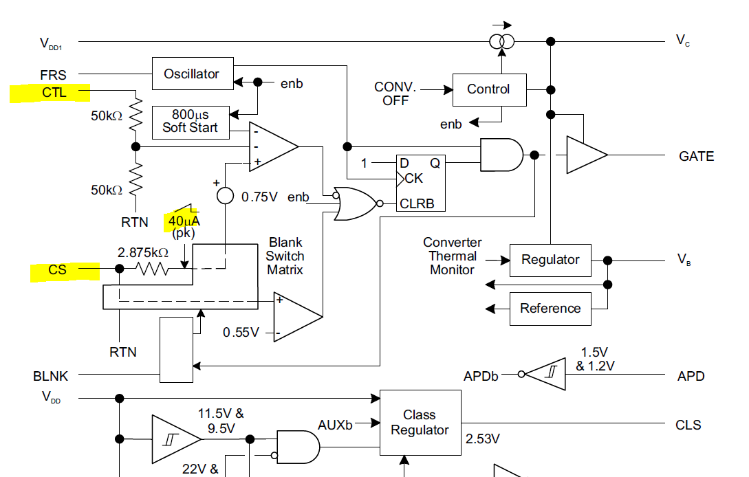
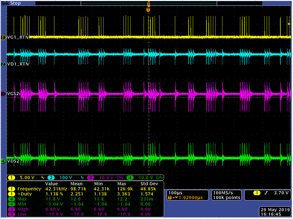
1. For the original EVM which is synchronous MOS at secondary side, why it will be CCM even load=0A? What’s the gate turn on/off criteria? When changed secondary MOS to diode SBR10U45SP5-13, it will into DCM when light load.
[MOS]0A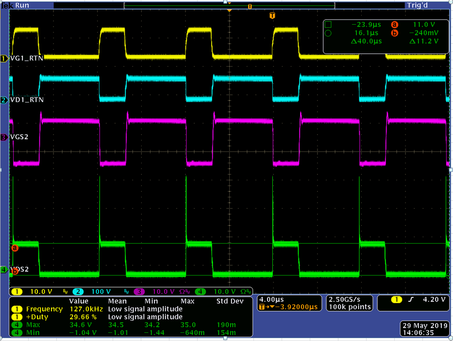
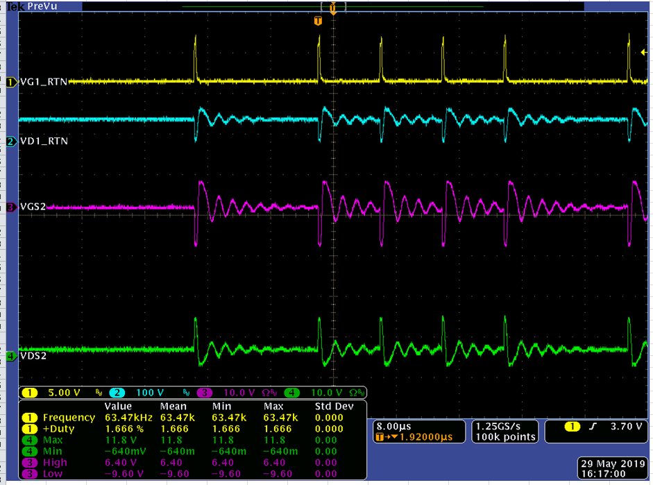
[Diode]0.5A
2.Why the VCS signal will be negative when using synchronous MOS at load=0A?
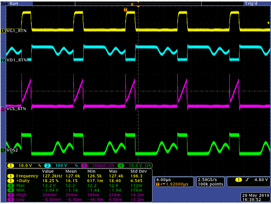
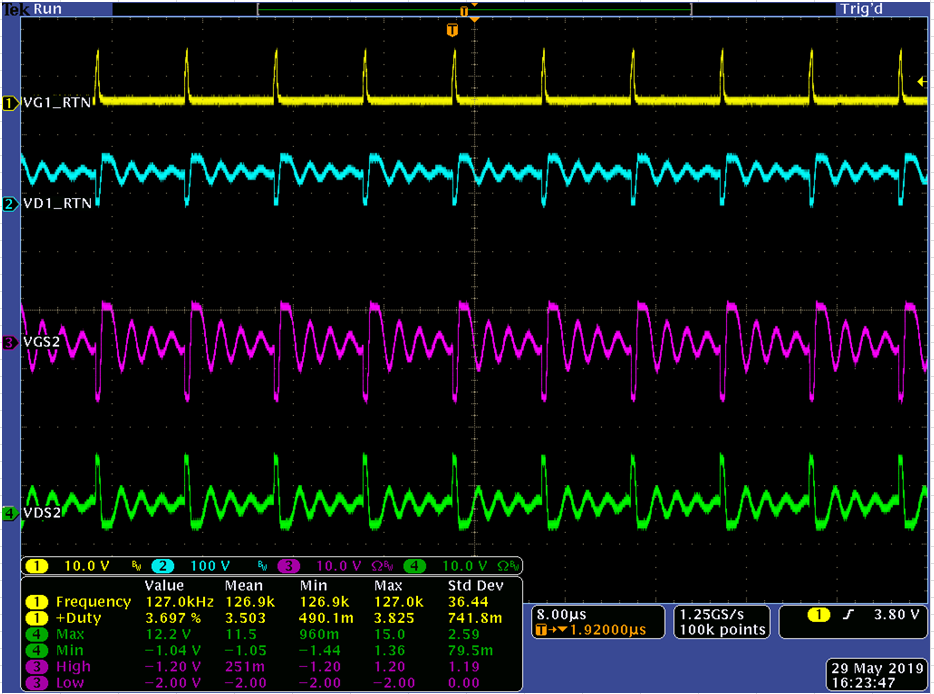
3. When use diode and the load=0A, we will see the gate like below(until load add to 20ma, then gate become stable and fixed frequency), Is that unstable?
(ignore channel 3, there's no gate due to diode)
[0A]
[20mA]
thanks.