This thread has been locked.

If you have a related question, please click the "Ask a related question" button in the top right corner. The newly created question will be automatically linked to this question.

TPS7B7701-Q1: the device(act as switch) shut down after 150s of power-on

Part Number: TPS7B7701-Q1

Dear team,

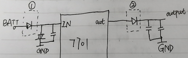
My customer uses the TPS7B7701-Q1 as a power switch. The schematic is as below, 

When they test it, they found some problems,

1. when this device acts as a LDO, the recommended output capacitor is 2.2uF-100uF. When this device acts as a switch, what are the recommended output capacitor values? Same with 2.2uF-100uF or different? If different, could you please tell me the recommended capacitor?

2. When the customer use this device as a power switch, the device shut down after 150s of power-on. At this time the Vsense's waveform is as below,

From the waveform, we can find that when the switch shut down, the Vsense=3.2V. According to the datasheet figure 19, the chip is in Reverse Current fault or Short to Battery fault. Could you please tell me the reason of shut-down? When does the chip detect these two faults? How often?

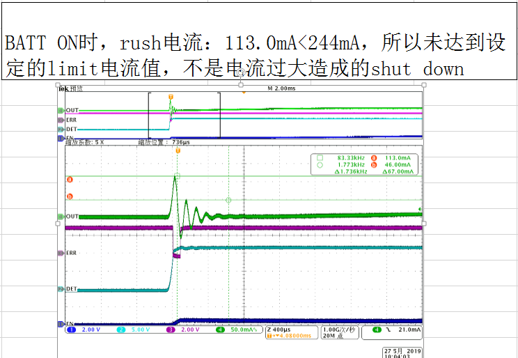
In addition, we also test the current as below, the rush current is 113.0mA smaller than 244mA which is the limit current value.

Thanks & Best Regards,

Sherry

  • Hi Sherry,

    1. when this device acts as a LDO, the recommended output capacitor is 2.2uF-100uF. When this device acts as a switch, what are the recommended output capacitor values? Same with 2.2uF-100uF or different? If different, could you please tell me the recommended capacitor?
    -- The swiched-mode bypassing the control loop of the LDO and no output capacitor is needed for stability. However, the current limit loop may require a capacitor to operate, please allow some time for me to get back to you on this because the current datasheet has little discussions on using the device in switched-mode.

    2. 2. When the customer use this device as a power switch, the device shut down after 150s of power-on. At this time the Vsense's waveform is as below. From the waveform, we can find that when the switch shut down, the Vsense=3.2V. According to the datasheet figure 19, the chip is in Reverse Current fault or Short to Battery fault. Could you please tell me the reason of shut-down? When does the chip detect these two faults? How often?

    --Once TPS7B770X device has been turned on and in normal operation. There is no short-to-battery(STB) detection but LDO is still protecting itself from reverse current. LDO will issue an error and latched off output when there is a current higher than 1mA sourcing into the device. Even TPS7B770X has the same fault table for STB and reverse current detections, we should be very clear that STB is only detected during turn-on sequence and once device is in regulation, there is only reverse current detection. When a test voltage Voutx is applied on output pin of a turned-on LDO, the reverse current value is a function of the difference of Vout voltage and test voltage Voutx, the inductor at output pin, the output capacitor and the load resistance. In order to generate the minimum 1mA reverse current detection, the required Voutx will be different.

    One way to identify if the failure is related to reserver-current ( and STB) or current limit is that RC and STB will latch the output; while current limit will not latch the output.


    Regards,
    Jason Song

  • Hi Jason,

    Thanks for your timely reply!

    According to the output which is latched, the reason should be the RC and STB, right?

    In addition, we also do some tests as below,

    1. Remove the output capacitor, and then the fault is eliminated.

    2. Add a diode on the output as below, and the fault is also eliminated.

    Could you please help explain this problem, RC or STB? If the fault is RC, what is the cause of the fault? Why is it related to the output capacitors? How do we resolve the problem? If the fault is STB, what is the cause? How do we resolve it?

    Thanks & Best Regards,

  • Hi Sherry,

    Based on your inputs, tt should be related to RC.

    1. Remove the output capacitor, and then the fault is eliminated.

    -- At the output, you have a LRC network. It seems to be that the LRC network is causing some kind of ringing together with the active antenna. In order to idenfity the issue, I would need to have some screenshots from you. \

     a, For the first scopeshot, please include input voltage and output voltage for your test. This will help to evaluate if ringing is exsited, we would like to know the amplitude of the peak to peak voltage. Please also include a current prob at the output of the LDO, this will help us to understand the flow of current caused by the active antenna together with the inductors.

    b. For the 2nd scopeshot, please repeat the thing on the first one but having the output capacitor removed.

    Regards,
    Jason Song

    2. Add a diode on the output as below, and the fault is also eliminated.

    --The added diode will block the current sources into the output of the LDO to trigger the RC pretection.

  • Hi Jason,

    The scopeshots are as below,

    1. with capacitor

    2. shut down with capacitor

    3. without capacitor

    Thanks & Best Regards,

    Sherry

  • Hi Sherry,

    Thanks a lot for providing the scopeshots. The startup with and w/o output capacitors look okay and it's not causing the problem. When looking at the scopeshot that LDO was shutting down with the output capacitors, it seems the reason for the output to latch is because of the sudden Vin drops. 

    Please see the area cycled in red. The sudden Vin drops causing Vin lower than Vout as in switched-mode, Vout is equal to Vin - Vdropout@Iload. When with the output capacitor, the output capacitor will slow down the drop on the Vout and this seems to cause the reverse current event that latches the output. 

    Can you help to find out at customer's boards, what happened at 150s that will dip the supply? Is it possible that the same battery is powering up other circuitry and the LDO is shutting down when another circuit has been started?


    Regards,
    Jason Song

  • Hi Jason,

    Thanks for your reply!

    Sorry, I didn't get your meaning about your last paragraph. Is it a problem of the battery?

    Thanks & Best Regards,

    Sherry

  • Hi Sherry,

    Based on the scopeshot you took, the problem seems to be that the supply Vin suddently drops. I wonder if you could find out if the supply is powering on something besides the LDO. Since in switched-mode, at no load, Vin is almost identical to Vout (Vout = Vin - Vdropout, at 0mA load, the Vdrop is near 0). With the capacitor, when sudden drop happens on Vin, Vout is supposed to follow but the capacitor is slowing things down. The voltage on Vout could be higher than Vin and this is causing the reverse current protection. 

    Regards,
    Jason Song

  • Hi Sherry,

    I modified one of my earlier reply regarding to the requirement of the output capacitors when used in switched mode. Please see updated answer here:

    1. when this device acts as a LDO, the recommended output capacitor is 2.2uF-100uF. When this device acts as a switch, what are the recommended output capacitor values? Same with 2.2uF-100uF or different? If different, could you please tell me the recommended capacitor?
    -- The swiched-mode bypassing the control loop of the LDO and no output capacitor is needed for stability. However, the current limit loop may require a capacitor to operate, please allow some time for me to get back to you on this because the current datasheet has little discussions on using the device in switched-mode.

    Regards,
    Jason Song

  • Hi Jason,

    Got it! I will check it with the customer. Thank you!

    Thanks & Best Regards,

    Sherry

  • Hi Jason,

    Ok.

    Looking forward to your reply!

    Thanks & Best Regards,

    Sherry

  • Hi Jason,

    Is there any result about the output capacitors?

    Thanks & Best Regards,

    Sherry

  • Hi Jason,

    Is there any process about the output capacitors?

    In addition, can I add a diode at the output as below? Will it influence the diagnostic function of this switch? My customer wants to use this solution to avoid the reverse current, is it feasible?

    Thanks & Best Regards,

    Sherry

  • Hi Sherry,

    We had a discussion here, and for the output capacitor, please refer to the capacitor recommendation currently on datasheet, which is from 2.2uF - 100uF.

    Adding the diode will help prevent the LDO entering the reverse current condion. Another way to try is to increase the input capacitor. I am only seeing 1.1uF capacitor at the input right now, can you try to ask the customer increase the size of input capacitor and try to see if the problem will be solved? 

    Have you heard from the customer on whether they are using the same power supply to power on other stuff? What exactly happens on the 150s where the problem started? This will help us to understand the issue and provide the best solution possible.

    Regards,
    Jason Song

  • Hi Jason,

    1. The battery also supply other devices. So when powering on, other module drops down the input power to around 9.5V which is still in the normal range. 

    2. About this questions, there are two solutions as below. Solution 1:  add a diode + An electrolytic capacitor(470uF) at the input; Solution 2: add a diode at the output.

    These two solutions both can solve the problem, but the customer are more inclined to the second option, because the solution 2 is cheaper.

    But I am not sure whether we can add a diode directly at the output, whether solution 2 will impact the diagnostic function of this device? Could you please answer this question?

    Thanks & Best Regards,

    Sherry

  • Hi Sherry,

    Thanks for sharing the customer's feedback and providing the detailed drawing on the proposed solutions.  Instead of having the diode at the output, I would suggest to have the diode at the input. When having the diode at the input, you may still have the same intput cap you have currently in the schematic. Here are the reasons. 

    1. Having the diode at the output is essentially adding additional ESR/ESL to the output capacitor. The device requires certain output capacitor and ESR range for stability.

    2. Having the diode at the input will help isolate the glitch at the input side. When the glitch happens on the supply, due to the sudden dip on the BATT, the input diode switch may become off when input capacitor is holding the voltage before the dip. Even when a load is exisited on the output when the glitch happens, the load will first discharge the output capacitor before the impacts get to the input voltage.It's not necessary to have a really big capacitor with the added diode.

    3. With the added diode on the input, it's not affecting the existing diagonostic functions of the device. When the diode is at the output side, the normal function of SENSE pin should work, but it will prevent the device to show the RC or short-to-battery as the diode is blocking those events from being sensed by the LDO. 

    Does it make sense to you?

    Regards,
    Jason Song

  • Hi Jason,

    1. If adding a diode at the output, this device won't detect the RC function, I understand this. But I don't understand why this diode will affect the short to battery detection which can be achieved by comparing Vin and Vout. The diode will only affect the voltage B.

    2. About the output capacitor, you mentioned before, it will affect the current limit loop. Could you please help explain more details about this?

    Thanks & Best Regards,

    Sherry

  • Hi Sherry, 

    1. If adding a diode at the output, this device won't detect the RC function, I understand this. But I don't understand why this diode will affect the short to battery detection which can be achieved by comparing Vin and Vout. The diode will only affect the voltage B.

    -- You are correct. If the short-to-battery is happening at point A, the device is able to detect it. But for real application, considering the cable is indeed in a car's chassis, a short-to-battery is likely to happen with worn-out cables and it's far from the LDO. It's less likely the short-to-battery can happen at point A. 

    2. About the output capacitor, you mentioned before, it will affect the current limit loop. Could you please help explain more details about this?

    -- In a linear regulator, there are multiple loops in design. An easy way to understand current limit loop is that it's one of the loops that control the pass-FET, when the output current exceeds a certain threshold, the current limit loop will turn off the pass-FET switch to reduce the output current. You can also consider this as a negative feedback loop and a negative feedback system requires certain conditions to be stable. 

    Regards, 
    Jason Song

  • Hi Jason,

    Got it! Thank you very much!

    Thanks & Best Regards,

    Sherry