This thread has been locked.

If you have a related question, please click the "Ask a related question" button in the top right corner. The newly created question will be automatically linked to this question.

TPS92641: TPS92641 issue

Part Number: TPS92641

Hi Sir

we use TPS92641 as Vin=24V, Vout=13.1V ,Iout=11A meet same questions, the SCH as attachment; pls help check it,tks!

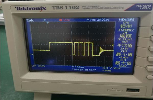
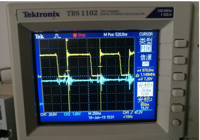
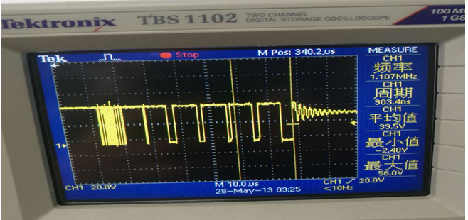
1.The following figure is the waveform diagram of the SW pin of the chip. There will be oscillation at the front end/end. What causes it?

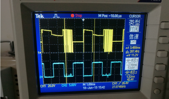
2. During the dimming process, the chip found that the lamp bead flashed. It was found that the PWM was at that point and the PWM duty cycle increased. However, the duty cycle value of the HG pin output was reduced. The output current is suddenly small, and the lamp bead flashes. In turn, the PWM will have a point from 100% to 0%. As the PWM decreases, the duty value of the HG pin output increases. At this point, the light will flash again. I will send a video as attachment,pls check it

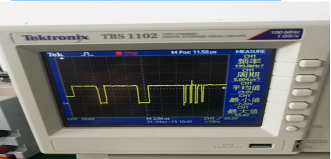
3.The debugging found that when the inductance is determined, the switching frequency is increased, this phenomenon will occur, the switching frequency will be lowered, and the waveform will be normal. What is the cause?

TPS92641-11A SCH.pdf

  • Hello Darren,

    1) Could you look at UDIM pin when this is happening and Vin at/near the TPS92641? There can be issues if the voltage at UDIM is near the UVLO threshold.

    2) This design will run into issues using UDIM at 6 KHz with a 47 uH inductor running 11A. The time it takes the current to ramp up in the inductor to 11A from 24V input, 13.1V output is about 47 uS. The PWM period is 166.7 uS. The control loop cannot stabilize since it is trying to deliver 11A when PWM goes high. At 25% duty cycle the current cannot average 11A during the on-time causing the compensation to increase. Try your PWM frequency at 200 Hz or so to see if it behaves different. If you need 6 KHz dimming perhaps Shunt FET dimming should be considered.

    The oscilloscope video appears to be a change of the trigger point on the waveform. The waveform doesn't appear to change just move.

    3) I'm not sure what this oscillscope picture is caused by. Can you look at the inductor current with these waveforms you have posted?

    C1 and C7 is not enough ceramic capacitor for your design, these are the capacitors that support the input voltage when switching occurs.

    Best Regards,
  • Hello Darren,

    I haven’t heard back from you, I’m assuming you were able to resolve your issue.
    If not, just post a reply below (or create a new thread if the thread has locked due to time-out)

    Best Regards,

  • Hi Irwin

    thanks for your help, the Vin:46V, Vout:39V/7.1A; PWM:400Hz IC work operating frequency :110KHz; our customer use your suggestons to layout new board and find the new issue as follow, could you help check it and give some suggestions for our customer how to debug it,tks!

    (1)Figure 1: CH1 is the SW pin waveform; CH2 is the UDIM waveform; PWM frequency: 400Hz;

    (2)Figure II:CH1 is the SW pin waveform; CH2 is the UDIM waveform; in this case, the SW has a high frequency oscillation output of 1.15 MHz;

    (3):Figure 3: CH1 is the SW pin waveform; CH2 is the SDRV waveform;

    (4)CH1 is the SDIM pin waveform; CH2 is the SDRV waveform;

    According to the specification, the waveform of the SDIM pin and the waveform of the SDRV pin should be inverted with each other;

    (5)Why is the waveform of the UDIM pin and the SDRV pin waveform inverted? With this output, what is the role of the SDIM pin? How to realize parallel dimming function?

  • Hello Darren,

    1)  That waveform looks okay though UDIM appears noisy it's probably just the measurement. 

    2)  What is Ron in your design?

    3)  What does Vin at the IC look like?

    4)  I don't understand this waveform, the SDRV pin should be a ground referenced gate drive, that is not what is shown.  What is the MOSFET you are using?

    5)  SDIM is inverted so when PWM is high the shunt MOSFET is off.  The MOSFET inverts, when gate is high the output is shunted.

    Are you using a combination of enable dimming and shunt MOSFET dimming?  What are you trying to do?

    Best Regards,

  • Hello Darren,

    I haven’t heard back from you, I’m assuming you were able to resolve your issue.
    If not, just post a reply below (or create a new thread if the thread has locked due to time-out)

    Best Regards,