This thread has been locked.

If you have a related question, please click the "Ask a related question" button in the top right corner. The newly created question will be automatically linked to this question.

LM2663: I apply +5.5V as V+, but Vout had been dropped to -4.3V with loading

Part Number: LM2663
Other Parts Discussed in Thread: LM2662

Hi,

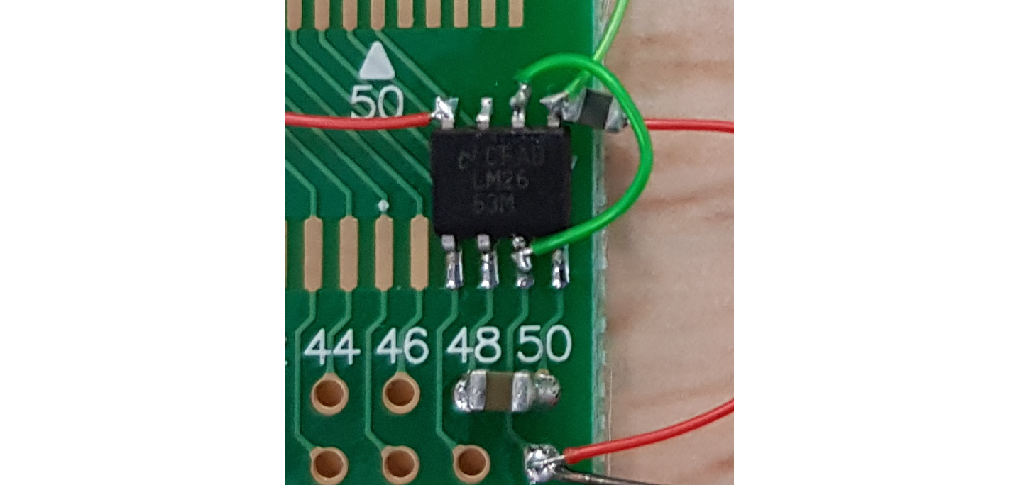
I want to know which conditions will make LM2663 Vout have a voltage drop?

I measured the output current was about 20mA, but I don't know why Voltage drop from -5.5V-->-4.3V when connected to LCD driver IC VSN?

  • The datasheet guarantees an output impedance of at most 7 Ω under the specified test conditions (47 µF low-ESR capacitors).

    What kind of capacitors are C19/C21? Are they right near the chip? (show the board layout)

  • Hi, Clemens

    Many thanks to your help.

    I used X5R 47uF capacitor for C19/C21. And I test LM2663 on PCB board like below picture show.

    But also found voltage drop down to -4.5V @ 20.6mA while connected to LCD loading.

    If LCD IC input pin have something wrong? to make LM2663 voltage drop?

  • The datasheet's layout guidelines say:

    • Place CIN on the top layer (same layer as the LM2662/2663) and as close to the device as possible. Connecting the input capacitor through short, wide traces to both the V+ and GND pins reduces the inductive voltage spikes that occur during switching which can corrupt the V+ line.
    • Place COUT on the top layer (same layer as the LM2662/2663) and as close as possible to the OUT and GND pin. The returns for both CIN and COUT should come together at one point, as close to the GND pin as possible. Connecting COUT through short, wide traces reduce the series inductance on the OUT and GND pins that can corrupt the VOUT and GND lines and cause excessive noise in the device and surrounding circuitry.
    • Place C1 on the top layer (same layer as the LM2662/2663) and as close to the device as possible. Connect the flying capacitor through short, wide traces to both the CAP+ and CAP– pins.

    On this board, there is no input capacitor, and all the traces/wires are long and thin.

  • Thank you Clemens for commenting and advising. 

    Hi Evan,

    Please follow Clemens' suggestion, and make a real PCB other than just soldering a few pins and using flying wires.

    Thanks,

    Youhao Xi, Applications Engineering