This thread has been locked.

If you have a related question, please click the "Ask a related question" button in the top right corner. The newly created question will be automatically linked to this question.

BQ24650: Charging error Solar/USB

Part Number: BQ24650

Solar_Power_Resize.pdf 

Hello All,

I've been working on a schematic to switch between Solar and USB power charging using the BQ24650. The schematic is available in file attached and it is recommended to take a look at it to understand the following lines.

I'm using a 6W, 6V solar panel and a 3.7V 12000 mAh Li-ion battery. My goal is to use first the USB power to recharge the battery via the 5V and only when there is no USB connection, the power management BQ24650 should use the solar power. To determine if the BQ24650 is recharging the battery or not, I've connected 2 LEDs to STAT1 and STAT2, STAT1 is for recharging status and STAT2 is for full charge status. 

When I connect the solar panel without the USB, the BQ24650 starts charging the battery when voltage from solar panel is more than 4.8V. STAT1 is always ON. There is no problem with this situation. 

However, when I connect only the USB, the MPPSET divider is changed in order to start working at 5V. Since the USB has priority, the voltage at VIN is around 5V.

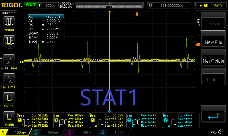
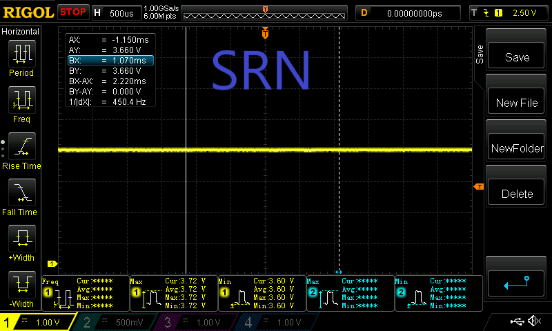
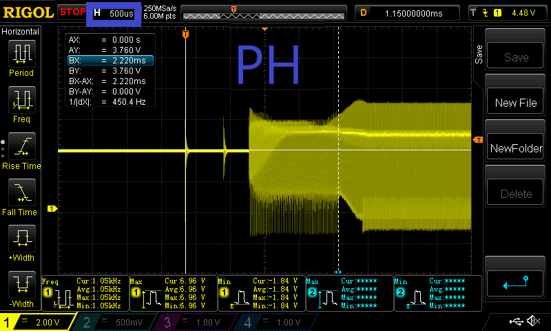
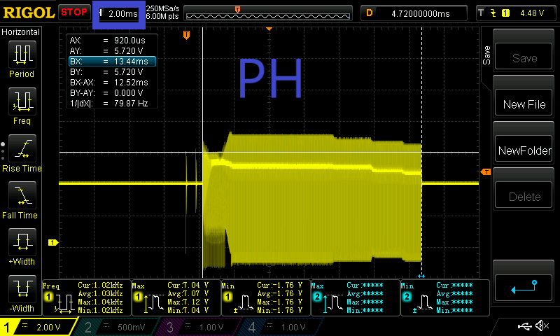
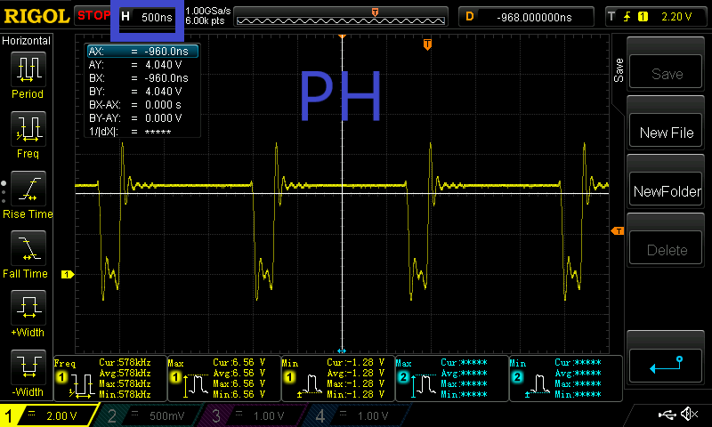
What I see is STAT1 led is blinking every 1s so the BQ24650 try to initiate the charge. I've tried to monitor the MPPSET voltage and it is more than 1.2V and the TS voltage is between 48% and 75% of Vref. The battery voltage is less than 4.2V (battery full regarding the 2 resistances R13 and R15 I m using).  

Another test was to use a power source to simulate the USB. Multiples conditions are needed to recharge the battery continuously.

First, the module doesn't work if Vusb is less than 5.2V.

Then, it start to charge only when the power deliver more than 1A.

Can you help me with this schematic problem ?

Best regards.

  • Hi Julien,

    I don't see an issue with the schematic except for the MPPSET circuit.  The MPPSET pin is the input to an error amplifier that controls input current.  If you disconnect this circuit from VIN and then use a separate power supply to control the MPPSET voltage, does the circuit function as expected with a USB source?

    Regards,

    Jeff

  • Dear Jeff, 

    I try to disconnect the VIN from the rest of the circuit and use a separate power supply to control the MPPSET voltage (1.2V or 1.3V). There are different behaviors. First, some USB source deliver only 5V (2A) and the BQ24650 don't start. When I use another USB power supply (which can deliver 5.08V), the STAT1 led has the same behavior as my previous tests, blinking...

    EDIT : 

    I've done 2  other tests.

    • I still disconnect VIN to control the voltage of the bottom left of the circuit and put 5.05V at V_USB. With this configuration, The BQ24650 seems to work (STAT1 is high permanently)  when VIN voltage is between 0.9V and 4.2V. When VIN is more than 4.2V, the STAT1 signal reproduce the pattern of blinking led every 1sec. Since in my design, I've connected VIN just after the diode PDS1040 (which as a dropout voltage of 0.4), the voltage at VIN is still around 4.6V>4.2V.  
    • When V_USB is 0V (disconnect USB power) and I connect a solar panel (SOLAR+ = 6V/6.5V), I measure the limits of VIN for BQ24650 to work. The charger controller is working properly when VIN is below 5.9V. When voltage is above this limit, the STAT1 signal is blinking led every 1sec.

    Any idea why the charger controller is acting like this ? 

    Best regards.

  • Hi Julian,

    Can you connect a power supply instead of the USB source, and ramp up VIN till charger starts to operate correctly? When doing so please capture VCC ramp (close to IC as possible), charge current, PH, SRN. Also please measure REGN and MPPSET on multimeter as VIN is ramped up. STAT1 blinking indicates charger is entering and exiting a fault condition. Possible fault conditions are listed in Table 2. STAT Pin Definition for bq24650 of the datasheet.

  • I try to connect a power supply instead of the USB source. When I put enough voltage at V_USB (5.1V), I try to ramp up VIN and see if it start correctly but it doesn't start at all. It can only charge around 5mA (just enough to turn a LED on STAT1) when VIN is between 0.V and 4.2V. This correspond to voltage at MPPSET low limit 175mV (regarding the datasheet) but also high limit when it's above 1.2V. When voltage at MPPSET is above 1.2V, the BQ24650 is entering an exiting a fault condition. 

    I think there is a mistake in the schematics but the presence of Q2 and T3 (the PMOS and the transistor next to MPPSET) are supposed to lower the MPPSET voltage divider in order to start the BQ even at 5V.


  • Hi Julien,

       When VIN is between 0 to 4.2V most likely the charger is in SLEEP mode where if input voltage is lower than SRN, then the IC will enter a low quiescent current mode. From calculating your MPPSET values, you have 2 MPPSET thresholds, at 4.289V (75k||39.2k top, 10k bottom) and at 4.704V (39.2k top, 10k bottom) where the 4.704V threshold is for the solar panel, and the other 4.2V threshold is for the USB right? What do you mean by MPPSET low limit and high limit?

         When STAT1 is blinking, can you take a scope capture of STAT1, VCC, SRN and PH? For all signals captures, probe pins as close to the IC as possible.

  • Hi,

    In order to be sure the charger is working correctly, I want to change the MPPSET threshold when I plug the USB source. My first MPPSET threshold for solar panel is (39.2k top, 10k bottom) 1.2*(1+39.2/10) = 5.904V.

    For the other threshold (75k || 39.2k top and 10k bottom) , as you mentioned it is 4.289V.

    What I mean by MPPSET low limit and MPPSET high limit, I measured the voltage at this point while ramping up the VIN voltage. I noticed the STAT1 stop blinking when this voltage (V_mppset) is out of the range 175mV and 1.2V.


    You can see the scope capture of STAT1, VCC, SRN and PH when STAT1 is blinking. The parameters are : V_USB = 5.1V / VIN = 5.1V and V_USB connect to VIN.

    There is multiples pictures of PH voltage measurements (different time scales) since I suppose this behavior isn't right.


    One thing that can be a huge information to take into account is when I scope the MPPSET with a probe to my oscilloscope, the charger is working properly, but when I don't, the charger goes back in fault mode.

    Could it be an impedance issue since when I connect my probe to MPPSET the input impedance is changing?

    Best Regards

  • Hi Julien,

       Can you attach the images on this post? I cannot open files from other sites.

  • You can see the images following : 

    Regards.

  • Hi Julien,

        When MPPSET is below 1.2V, this means the charger is in MPPSET regulation and trying to regulate the voltage. In this voltage regulation loop, the input voltage is regulated, and charge current is reduced to maintain input voltage at the MPPSET point. Most likely your transistor implementation of MPPSET is not working as expected when USB is connected. Looks like the MPPSET point for solar panel (this input source operates correctly) is also being used when USB is connected, causing charger to be in input regulation until you ramp up the input voltage. What is the input voltage and MPPSET voltage at the moment STAT1 stops blinking and charging occurs normally?

  • Hi Julien,

      Any updates on the test mentioned above? If your issue has been solved, please let us know root cause and solution. 

  • Hi,

    My PCB is no longer working right now, I will receive a new one next week. I will try to do the measurements and tests as you recommended me as soon as I can.

    Then I will post an update to get you in touch. 

    Best Regards 

  • Hi Julian,

       Sounds good. For tracking purposes I will close this thread for now. Please re-open this thread when you are able to evaluate your new PCB.