This thread has been locked.

If you have a related question, please click the "Ask a related question" button in the top right corner. The newly created question will be automatically linked to this question.

UCC27714: High side output goes into OFF state during 3-phase sinusoidal based current control operation.

Part Number: UCC27714

Hello TI, 

I have designed a three phase inverter for operating current control to an 3-phase inductive load(2.2mH per phase). Operation is stable at 60V and upto 16A rms current. If i increase my input DC link voltage to 72V and at 6A rms current, output of the high side driver gets OFF for few pulses but input to the driver is proper. While debugging the circuit, i.e checking the bootstrap voltage( constant voltage 15V throughout i.e No issues) and the pulses at the input and output, the pulses from the controller to the driver (proper SPWM from control to the input to the driver), the state where high side output pulses went to the OFF state, there we could see that it somehow went little below then 0V.

I have attached the image during the OFF state of the high side pulse. Green pulses are the high side driver output pulses and Red pulses are the high side driver input pulses.   

If the issues as suggested by application note of UCC27714 is the Undershoot voltage then for the same circuitry, i have increased my output gate resistance to 15ohms for initial 10ohms and also added schottky diodes to between HB and Ho and also between HO and Hs. But still the problem is resolved.

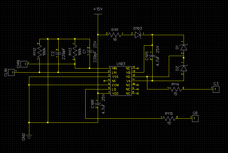
I have attached schematic as a reference for my driver circuitry with all the R and C parameters with their ratings.

As the output of the High side driver gets into OFF state, the output of my phase currents drops down.

I have attached output of phase current and in the attachment we can see that because of OFF state in high side driver the current in Blue phase drops down. And current in yellow phase and red phase in normal but it also gets hampered at voltage above 80V.

  • Hello Jeet,

    Thank you for the interest in the UCC27714 half bridge driver. I am an AE with the High Power Drivers group and will help to resolve the issues.

    For the LI and HI inputs is see you have filter capacitors, and it looks like parallel resistors to ground, I would suggest to have some series resistance to provide some R/C filtering for the driver inputs.

    I sounds like you have reviewed the datasheet for advice on addressing this behavior that may exist in some applications. For the D1 and D1 diodes, confirm that these are small package devices located as close as possible to the UCC27714 IC pins. Also the diode should be low Vf, usually 1A rated 20 to 30V rated Schottky diodes should have low Vf to more effectively clamp the HO output.

    As a suggestion for troubleshooting I would try two things. 1) Confirm if HO clamp diodes are appropriate part and close to the IC pins with short trace connections, if not relocate the devices close to the IC, for experimentation purposes. 2) Increasing the gate resistance helps these issues in many cases, continue to increase the gate resistance, to see if this helps resolve the issue.

    Let me know if this addresses your questions, or you can post additional questions on this thread.

    Regards,

    Richard Herring

  • Hello Richard,

    I tried your method and results are good for 90 V but, once i increase my DC link voltage again the waveform cuts. Could you forward PCB layout of complete driver (ucc27714)with schottky placed .

    Thank you.

  • Hello Jeet,

    It sounds like there has been some improvement in the operation from before. The diodes should be placed close to the IC, as well as the boot strap capacitor should be placed close to the IC HB and HS pins.

    See the attached file which is the datasheet layout example with diode symbols shown in yellow added. It may help to adjust the gate drive resistance, increase the value, as this will help dampen the ringing and will further limit current into the IC pins from the voltage undershoot or overshoot.

    See the attached file for reference.

    Please confirm if this addresses your concern, or you can post additional questions on this thread.

    Regards,

    Richard HerringUCC27714 output clamp diodes.docx