This thread has been locked.

If you have a related question, please click the "Ask a related question" button in the top right corner. The newly created question will be automatically linked to this question.

LMG1205: RE: LMG1205: Operating LMG1205 with external supply to achieve 100% duty cycle

Part Number: LMG1205
Other Parts Discussed in Thread: SN6505B

Hi Don,

I was unable to reply to the previous post (just a blank page when I clicked on it), so I have created a new thread.

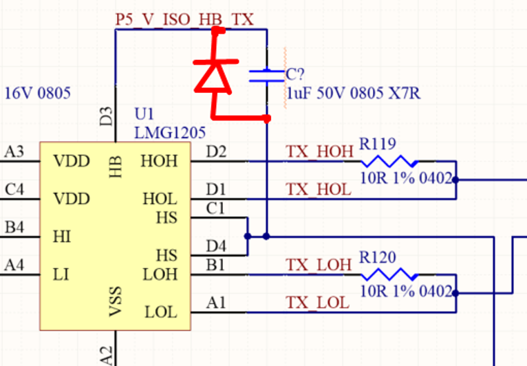
In answer to your question, this is our schematic.  We have used this successfully in the past to achieve <50ns rise/fall times in a pulsed system at around 10 to 20% duty cycle.  We are interested in being able to run this circuit up to 100% duty as we have some test modes where the customer wishes to have the load permanently on.  This is not a conventional power supply application, rather we are switching the drain supply of a RF amplifier which runs at 5V.  For other applications we sometimes wish to run at 20 or 30V drain supply. (we are also planning to increase the bootstrap cap to ~1uF and Vdd bypass to 10uf)

Kind regards

Mike

Hi, Mike,

Thanks for your question, and your interest in our gate drivers.

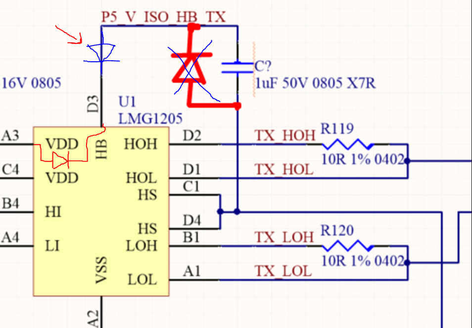
It needs to be a little more involved than a resistor. The issue is when you turn off the high-side, the voltage will increase past the voltage rating of the EPC2108's gate and damage it since you would be circumventing the protection we have built in the LMG1205.

You might be able to do something like this, but the difficulty is going to be to keep the output voltage within safe limits for the LMG1205's gate voltage limits.

Alternately, can you switch at like 99% duty cycle to allow the bootstrap cap a chance to recharge?

Can you share a little more about your application?

  • Hi Mike,

    Sorry for the confusion with the previous thread. Thanks for your interest in LMG1205. I work on the applications team in the high power drivers group and can help you with your question.

    I’m not sure what was said in the other thread and what options are feasible.

    For 100% duty cycle operation, you will need some kind of isolated supply or charge pump circuit, referenced to the switch node. As Don said, eGaN FETs are pretty sensitive to EOS, so I would recommend a pre-regulation circuit to ensure that this isolated rail stays at 5V. This will also reduce stress on the internal 5V clamp in LMG1205.

    This paper goes over a 5V isolated supply using SN6505B and LP2981-5.0 to generate a steady 5V rail. This circuit should work for your 100% duty cycle requirement.

    http://www.ti.com/lit/an/sbaa268a/sbaa268a.pdf

    If this answered your question, could you please press the green button? If not, please feel free to ask more questions.

    Thanks and best regards,

    John


  • Hi John,

    That is really helpful, thank you for your response.  We had considered adding an isolated power supply,but weren't fully sure how to do this, for clarity, I have sketched out the connections into the LMG1205.. is this where you would expect to connect the isolated supply into the circuit?

    Kind regards

    Mike

  • Hi Mike,

    Those connections look correct; +5V connected to HB, digital GND connected to HS, directly across C194.

    If you are worried about how the isolated supply and internal bootstrap diode will interact with each other, it is possible to isolate the internal bootstrap diode by placing another diode with anode on C194, and cathode on HB. The isolated supply would still be placed directly across C194.

    It will be important to ensure that routed area for this circuit is kept low, in order to reduce the parasitic capacitance placed on the switch node.

    If this answered your question, could you please press the green button? If not, please feel free to ask more questions.

    Thanks,

    John

  • Hi Mike,

    thanks for your reply, I work with John and will try to help out.

    That correct, you may have to put a current limiting resistor in series with the output to keep HB within reasonable limits if there is ground bounce or during power up when the bootstrap current is highest. Standard bootstrap considerations will still apply since ground bouncing can increase the bootstrap voltage, which can stress the high-side supply. However the high side UVLO startup delay will no longer be there due to the isolated supply being present.

    If 100% duty cycle is used, VDD quiescent current continues to draw. This current is sourced by the bootstrap capacitor. Over time, the bootstrap capacitor will be depleted. 100% duty cycle is possible as long as the VDD voltage remains at an acceptable level. Increasing the size of the bootstrap capacitor increases the stored charge, which increases the duration for which 100% duty cycle is possible. If indefinite high side 100% duty cycle is required and a 99% duty cycle can’t be used to periodically replenish VDD voltage before it falls below an acceptable drive level, or below the VDD UVLO threshold, a separate isolated supply will be required for the high-side driver which will need to be able to constantly supply current per the larger value of the bootstrap capacitor.

    please let me know if you have any more questions!

    thanks,

  • Thanks John,

    We were a little concerned about that, I will put a placeholder in the circuit for a diode as described..just for safety.

    We will also look to minimise the circuit size as much as possible and aim to minimise parasitics where possible.

    Really appreciate your input here, thanks.

    Also, thanks to Jeff for the response below, I will add a series resistor placeholder to allow for some experimentation here if required.

    Kind regards

  • Hi Mike,

    Sorry for the confusion, but the diode drawn in the picture above is in the wrong place.

    I meant to add the diode as drawn below. I also drew the internal bootstrap diode just to help show what this blocking diode is meant to do.

    Thanks,

    John

  • Thanks John,

    That makes sense.  I will mark this as closed now.  I appreciate your help.

    Kind regards

    Mike