This thread has been locked.

If you have a related question, please click the "Ask a related question" button in the top right corner. The newly created question will be automatically linked to this question.

UCC28070: UCC28070 behaviour

Part Number: UCC28070

Hi,

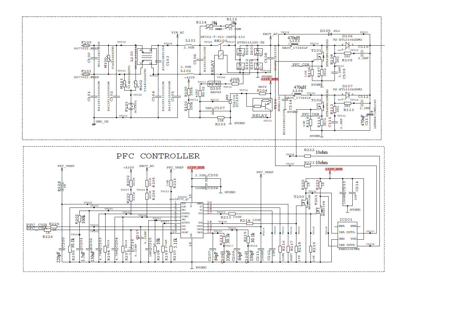
We are using UCC28070 IC for power factor correction in our on board charger design whose rating is 1kW. while evaluating PFC circuit we observed that for a very low load current also IC is firing mosfets with more than 50% duty cycle and also the output of PFC (420V) is droping from 420V to 330V. Seams its duty is getiing saturated. We have selected all the components as per the excel calculator except for current transformer (we have used shunt resistor of 120mohm). Please suggest what could be the reason. 
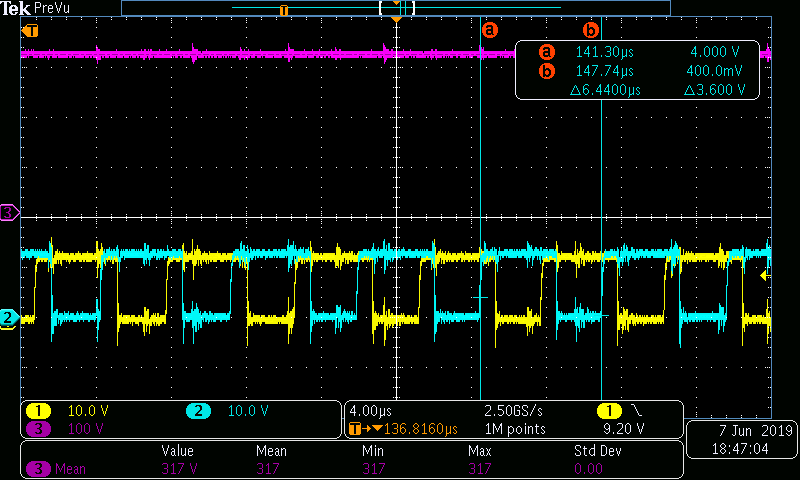
I am attaching our calculation with this post as well as plots captured on GDA and GDB.3666.UCC28070 Design Tool _RevA.xls

  • Hello Jyoti,

    The Dmax is set for 0.9 so the waveforms you attached are not extra ordinary.

    But the output voltage is unstable and some component is probablynot set properly

    The calculator was designed for use with a current transformer . I noticed that you used the calculator and set the turns ratio as 1:1 and a sensed voltage of 

    of 2.06V. Are you not using an OPAMP with this circuit ?

    One of the component values the calculator computest is the RSYNTH value.

    I wonder if this is not set properly

    Can you post ta pdf of the schematic ?

    Regards

    John

  • Hi John,

    Thanks for replying! 

    Yes we have not used current transformer or opamp. Voltage across shunt resistor is directly given to CSA and CSB pin for current sensing. I have attached Excel calculator again with schematic as shown below. I have selected value of Rsynth, Rimo and loop compensation components in current loop as per the formula suggested in application note/datasheet. Please suggest if the same formula can be used when current transformer is not used. if not, then what would be the correct approach. 0245.UCC28070 Design Tool _RevA.xls

  • Hi john,

    In one of your Q&A you had replied that if we are using low side shunt resistor to sense inductor current instead of current transformer then  for calculating value of Rsyn we need to use below formula-

    Rsyn = 10*Ipri*L*k/Vs

    But when i put value I am not getting positive value. Peak current is  15.288A, boost inductor Lmax=541uH, k=3.16kohm/(3.16kohm+442kohm), Vs is selected as 2.06V. We are using 120mohm shunt resistor.

    Please suggest how to select value of Rsyn.

  • Hi Jyoti,

    I calculated 279kOhms with this equation 

    I dont see how you could have reached a negative value.

    Also if the peak current is 15.3A and the sensed voltage Vs is 2.06V then the shunt value should be 2.06/15.3 = 134 mOhms.

    Not 120mOhms

    With 120mOhms  you should use a sensed voltage of 1.8 V

    Regards

    John