This thread has been locked.

If you have a related question, please click the "Ask a related question" button in the top right corner. The newly created question will be automatically linked to this question.

UCC5350: UCC5350MC schematic with +18V and -3V power supply

Part Number: UCC5350

Hi

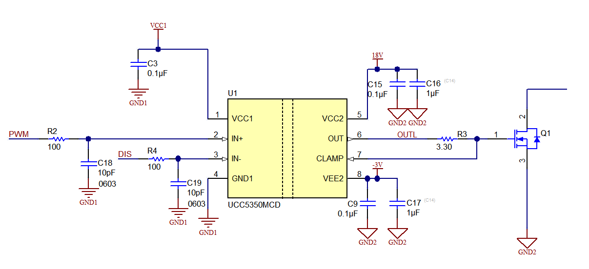
my customer want to use UCC5350MC with miler clamp.

  1. the driver power supply is +18V and -3V, could you help to draw the schematic how to connect UCC53x0MC with SiC MOSFET?

  2. What’s the response time of Miler Clamp?

  3. Customer need a disable pin, could he use IN+ or IN- as a disable pin?

thanks.

  • Hi Max,

    I work on the applications team in the high power drivers group and can help you with your question.

    The connection of the UCC53x0MC device is very similar to the negative drive application circuits found in section 11.2.3.3. You can use a dedicated supply, or a zener drop circuit. See the schematic below for an example.

    The miller clamp is turned on when the gate-to-source voltage drops below the clamp threshold voltage (2.1V typ). We don’t have a spec for this, but it is controlled by a comparator which switches very quickly, and should be fully on before the drain-to-source voltage starts to slew.

    Please see this tech note, covering how to use the inverting input as a disable pin.

    http://www.ti.com/lit/an/slla423/slla423.pdf

    If this answered your question, could you please press the green button? If not, please feel free to ask more questions.

    Thanks and best regards,

    John