This thread has been locked.

If you have a related question, please click the "Ask a related question" button in the top right corner. The newly created question will be automatically linked to this question.

BQ24105: Charger start up

Part Number: BQ24105
Other Parts Discussed in Thread: BQ24130

Hello,

I am using the charger in an application where i have 3 series schottky diodes on the output of the charger and the feedback network is connected after the diodes to compensate for the diode drop. The charger is inside the battery pack and the cell is always connected after the 3 diodes. when i provide power to the charger, it goes into hiccup mode (different from the detection) and never recovers.if i short the diodes then the charger works normally. I need the series diodes for protection and cannot get rid of them. 

Also, when the diodes are connected but the cell is disconnected, the charger enters the detection pulse mode and depending on what level of the pulse i connect the cell, it chargers or not. for example if i connect the cell when the pulse is at 0V it doesn't latch but when i connect the cell when the pulse is at the positive level, it engages and charges every time.

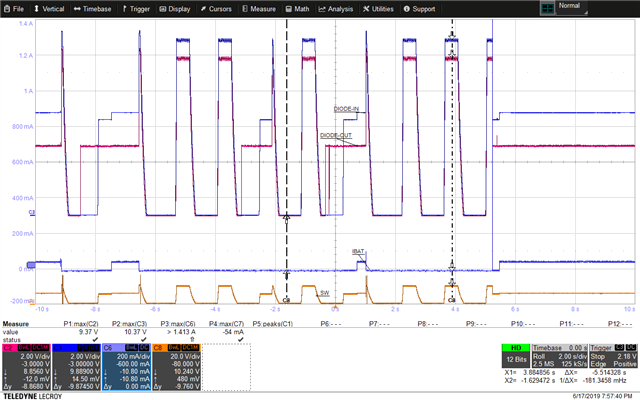
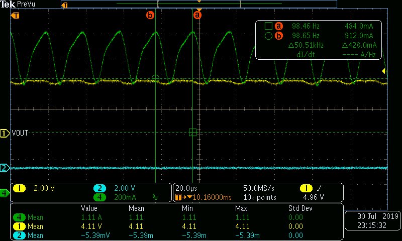
I am attaching the scope plot of the hiccup and also a snapshot of the schematic.

please help!

  • Hi Gaurav,

    We have never tested the charger in this configuration so I cannot warranty operation.  That said, the circuit might function if you add additional capacitance between the 0.1ohm resistor and first diode.  What are the diodes protecting against? 

    Regards,

    Jeff

  • Hi Jeff,

    Thank you for the response. The diodes are protecting the cell discharge into the exposed contacts in case the chip fails and there is a possibility of shorting the exposed contacts in a hazardous location. this protection is required for an intrinsically safe battery pack.

    I shall try your suggestion. there is 1 more observation, when i pull the TTC pin to ground (essentially disabling the timer and termination), I can get it to work every time even with the shottkys in place. 

    any insights into this?

    Thank you,

    Gaurav

  • Gaurav,

    Based on the datasheet explanation of TTC pin functionality, I would not expect it to have any effect.  What do the waveforms before and after the diodes look like when TTC is being used vs. shorted? 

    Regards,
    Jeff

  • Hi Jeff,

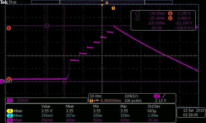
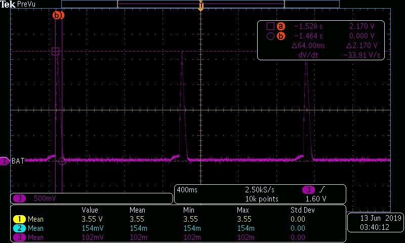
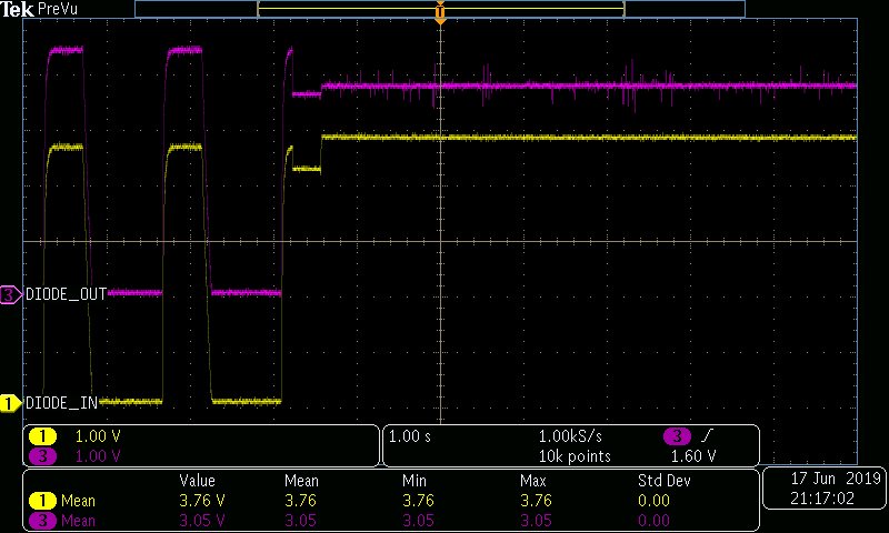
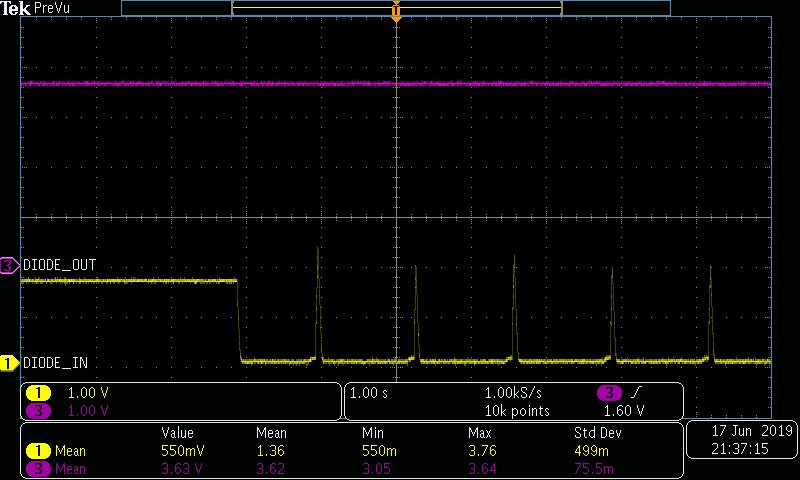
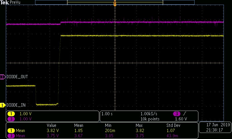
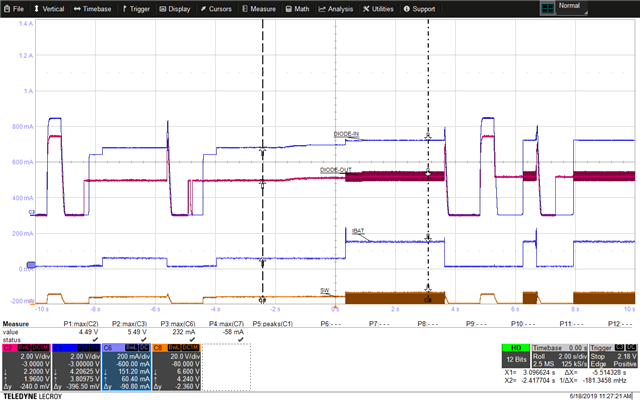
    the scope shots are attached below.

    1. Battery connected and charger ON:

    2. Battery disconnected, charger on, battery connected on -ve pulse:

    3. Battery disconnected, charger ON, battery connected on +ve pulse:

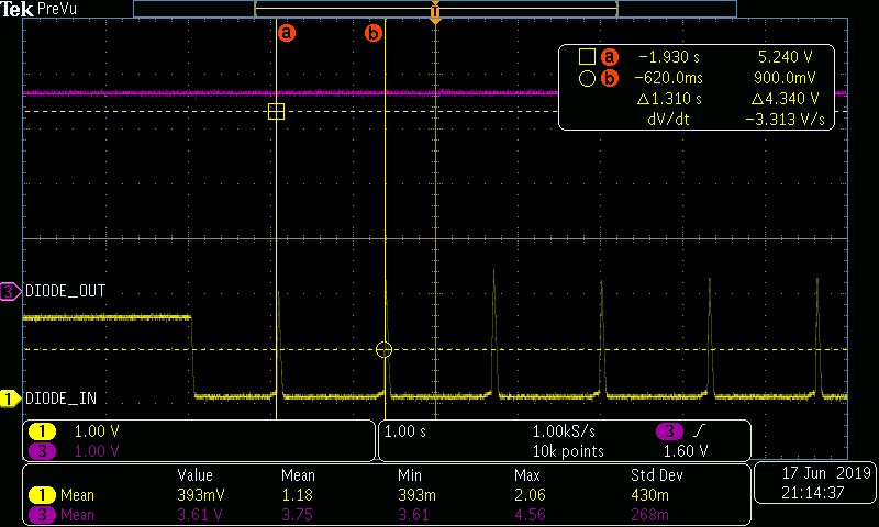
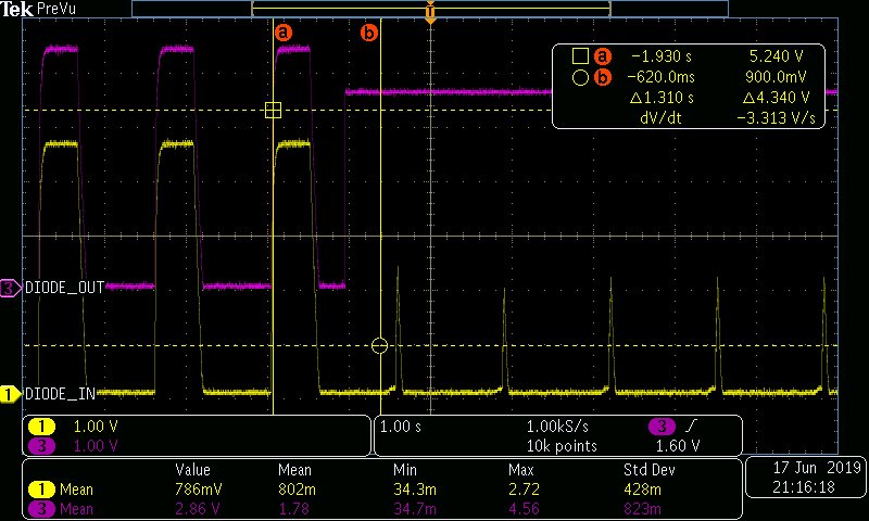
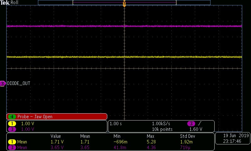
    The TTC waveform will attach in the next reply as it is not longer allowing more attachments.

    Thank you,

    Gaurav

  • Hi Jeff,

    1. Battery connected, TTC pulled high, charger ON:

    2. Battery connected, TTC pulled low, charger ON:

    Thank you,

    Gaurav

  • Gaurav,

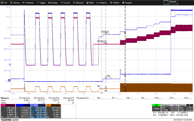
    The timing of the pulses is suspiciously close to battery detection time; however, shorting TTC to ground does not disable battery detection based on my testing of th EVM.  When I modified a BQ24105 EVM by removing the 200kohm surface mount top FB resistor with 600kohm through-hole resistor and connect the resistor to the output of three diodes, I cannot reproduce your issue.  In fact my EVM with the diodes functions as I expect per plots below.   My EVM is powered by 15V and I attached a simulated battery. Are you attaching a real 3-cell battery that is deeply discharged or a batterysimulator? 

  • Hi Jeff,

    I am using the default configuration for the BQ24105 as a single cell charger. so i just replaced the top 200k with a TH resistor to connect to the output of the diodes. The output regulated voltage is 4.2V. i am using an actual 18650 battery cell that is connected to the output of the charger (after the 3 diodes). The input to the charger is from a 6V power supply current limited to 1.5A. The cell voltage is around 3.3V.

    In your setup are you connecting the battery emulator after the charger is ON? can you try configuring the charger for a single cell output and turning on the battery emulator prior to powering on the charger?

    also, in the 2nd scope plot, the battery current stays around 50mA, whereas in the 1st plot it reaches to 1.33A. why is that?

    if you connect the cell or the battery emulator prior to turning on the charger, the scope plot should start with the cell voltage on the diode output and the charger should never enter the battery detection (this is what I observe when the short the 3 diodes).

    Thank you very much for putting in the effort to prototype the circuit. 

    Best Regards,

    Gaurav 

  • Hi Gaurav,

    I reproduced with 4.2V battery. I tried both PS on first and battery emulator on first.  Please see below.

    At V(BAT) < VSHORT, current is ISHORT = 35mA-65mA current source.

    At VSHORT < V(BAT) < V(LOWV), current is reduced to precharge current.

    V(BAT) is measured at FB pin.

    Regards,

    Jeff

  • Hi Jeff,

    Your configuration seems to be working as expected.

    thanks for the feedback. what voltages are you seeing on the diode in and diode out if the charger is off (no PS) but the battery is connected to the output?. i am seeing 3.65V on the diodes out which is the expected voltage of teh cell but at the input i am expecting the same voltage but I am seeing 1.71V which indicates that there is a leakage path from the feedback pin to the Bat+.

    Can you confirm if you are seeing the same thing or not. what kind of diodes are you using?. i am using the MBR340 schottky.

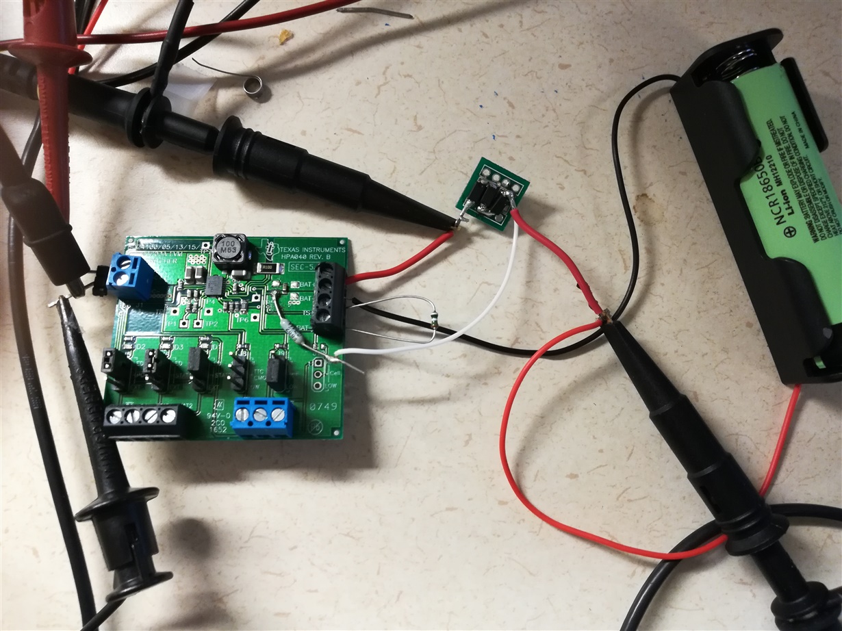
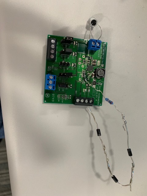
    Also, below is the picture of my setup. can you please check if it is OK. i have connected a 10k between TS pin and Bat- to see if ti makes a difference but it doesn't.

    Thank you,

    Gaurav

  • Gaurav,

    Your setup looks like mine only I used MUR120 through hole diodes.  I did not measure on the input side of the diodes (BAT+ on the board) when there is no input power.  The BAT pin connects at BAT+ on the board.  The is a small leakage path [I(SLP) < 10uA] into the BAT+ and SNS pins. 

    Regards,

    Jeff

  • Jeff,

    I really don't understand why the system works in your setup and not in mine. I really want to use this part in this application. i would have thought it should be easier with the schottkys as the Vf is significantly lower than the switching diodes...maybe switching speed comes into play too??

     I will try with switching diodes tomorrow. anything else you think I might be missing?. can moving the sense resistor after the series diode help?

    Thanks for your help.

    Gaurav

  • Gaurav,

    I have ordered another EVM that I will modify just to confirm mine was not a fluke.  I noticed that the feedforward capacitor C3 is still on your board connects before the diode to FB.  Can you remove and retry?

    Regards,

    Jeff

  • Jeff,

    So is this capacitor not populated on your EVM board?. can you send me a picture of your setup to compare?. I am wondering if i am missing some other things too. 

    Thank you,

    Gaurav

  • Gaurav,

    Please see below.  Also, I do not have the feedforward diode installed.  If installed it would need to be after the diodes.  I have ordered new diodes and a new PC which I will use next week to reproduce.

  • Hi Jeff,

    You nailed it!. it was in-fact the feed-forward capacitor causing me all this grief. 

    Thank you for all the hard work you put in to support this application. I consider this issue closed.

    Thanks again,

    Gaurav

  • Hello,

    is there any charger which does not have the pulse train for battery detection? after extensive testing, this solution seems to not work sometimes when the output stays low even after the battery is connected and wont charge after that.

    Thank you,

    Gaurav

  • Gaurav,

    I am not aware of a charger with FB pin that does not have battery detect.  Have you tried increasing the output capacitance above the maximum per the datasheet in order to defeat detection?  Does disabling termination with TTC pin also disable battery detection?  I am traveling or would test in the lab for you.

    Regards,

    Jeff

  • Gaurav,

    I tested on the bench and pulling TTC pin low does not disable battery detection.  If you toggled /CE, does charge restart?

    Regards,

    Jeff

  • Hi Jeff,

    toggling the CE pin doesn't help. i was looking into BQ24130 and it seems like it does have a separate battery sensing pin (other than CISP and CISN) and doesn't have battery detection. can you please confirm?. is there an EVM available?

    also, it doesn't look like it has a end of charge detection based on either the charge current or timer, correct?

    Thanks,

    Gaurav

  • Gaurav,

    If there is no pack the battery detect discharge phase will not work because of the diodes.  So likely it is detecting a battery even though there is not one there.  Then if the charger thinks it’s terminated and when you plug in a battery greater than VRECHG it would not start a new charge cycle.  But toggling CE should restart a charge cycle. Do you think that was what was happening?

    BQ24130 is another option. I am not as familiar with this device.  I will sample an EVM and test on the bench next week.

    Regards,

    Jeff

  • Hello Jeff,

    is there a way to control the fast charge current on the iset pin from a pwm signal from a host microcontroller? 

    Thanks,

    Gaurav

  • Gaurav,

    BQ24130 does not have battery detection.  I plan to modify and test your circuit on the BQ24130 tomorrow.  What was the exact issue with the BQ24105 that I need to watch out for?

    The voltage at ISET pin sets the charge current. You can inject a DC voltage (RC filtered PWM signal) through resistor to dynamic change the charge current.

    regards,

    Jeff

  • Jeff,

    with the bq24105, sometimes the battery doesn't get detected and the output after the 3 diodes stay at battery voltage and no charge current is seen. hopefully this will not happen with the BQ24130. 

    also the BQ24130 has an option of power path management but the datasheet does not indicate how the mosfets isolating the DC in and the battery are controlled. is there an application note or design ideas on how this can be done? in case of the BQ24105, the PG output is used to control the power path according to the app note SLUA376.

    let me know how the experiment goes. I shall order an EVM from digikey and do the same,.

    Thanks,

    Gaurav

  • Gaurav,

    use BQ24130 is intended to be used with a host processor.  The processor's GPIOs control various pins, including the power path FET.

    Regards,

    Jeff

  • Jeff,

    any luck with testing the BQ24130? my EVM hasn't arrived yet.

    Thanks,

    Gaurav

  • Gaurav,

    Yes.  I tested yesterday on the bench and it appears to work. 

    As a side note, I repeated my testing of the BQ24105 and I don't see the issue you are seeing.  The charger starts charging whenever I remove and replace the battery.  The only non-ideal operation is that when you remove the battery, the output of the charger remains high and doesn't re-enter battery detection unless you toggle CE or remove and replace input power. 

    Regards,

    Jeff

  • Jeff,

    Thanks for the feedback.

    on the 24130, did you use a resistor divider for the feedback or just direct connection from the output of 3 series diodes?. 

    on the 24105, what feedback resistor values are you using?. i have 1 modified EVM that works every time and charges the battery no matter at what level of the detection pulse i connect. it also goes into the battery detection pulse mode once i disconnect the battery. The problem though it that once fully charged, the BAT pin is at the same potential of the f/b pin (around 2V) and so even if the battery voltage decreases i don't see it enter the recharge mode.  

    i have another 24105 EVM with the exact rework that doesn't work and needs me to sync the battery insertion with the positive going edge of the detection pulse. 

    i tried another rework wherein i introduce the 3 diodes right after the L-C filter and have the current sense resistor connect after that. the advantage is that the BAT pin and f/b pin are at the same battery potential. i get this configuration working every time but i am concerned about the stability. do you see any immediate concern with this configuration?R11 is DNP.

  • Gaurav,

    I'm using 200kohm resistors.  The discharge current for battery detect algorithm goes into the BAT pin.  I suspect that was the issue.

     I will send the circuit above to the designer to confirm but I don't see an issue.  I suggest adding capacitance after the current sense resistor.

    Regards,

    Jeff

  • Jeff,

    for the BQ24105 charger, is there a way to control the charge current on the ISET pin from the host processor? does it follow similar setting as the BQ24130?

    Thank you,

    Gaurav

  • Gaurav,

    I checked with my designer and he doesn't see any obvious issues with placing the SNS resistor after the diodes.  Regarding ISET pin, you can inject a voltage from a DAC through a series resistor to the ISET pin to adjust charge current.

    Regards,

    Jeff

  • Hi Jeff,

    for the BQ24105, i don't think the charge current can be adjusted by varying ISET1. i disconnected the 7.5k from ISET1 and connected it to an external power supply set to 0.8V. the output voltage and charge current were both cycling. it recovered when i put the 7.5k back.

    can you confirm?

    Thank you,

    Gaurav

  • Gaurav,

    You cannot drive the ISET1 pin directly.  You will need a resistor to ground and then a DC voltage connected through another series resistor to ISET1.  ISET1 is the output of a current source. If you try to overdrive without the ballast resistors, the charger will not be stable.  I just confirmed on the bench that it works.  I will have an equation for you on how to size the external resistor and DC voltage tomorrow.  The DC voltage needs to be clean (little ripple) and somewhat precise. 

    Regards,

    Jeff

  • Jeff,

    sounds good. please also include a rough schematic of the connection if you don't mind.

    Thank you,

    Gaurav

  • BQ24105_adj_ichrg.pdfGaurav,

    Please see attached.  It is simply a resistor (RINJ) and DAC voltage (VINJ) that injects current into ISET1 with RISET1 installed. VINJ max is the lower of the voltage that reduces charge current to zero or 3.0V.   As mentioned previously regarding the diodes, we haven't done extensive testing, and therefore cannot warranty all of the datasheet specs, but both the diodes and this injection circuit should theoretically function.   

  • hmmm, very interesting. practical application of the Kirchoff's rule...:)

    i shall try and update. thank you.

    Do you have an altium based footprint for the BQ24105 IC?

  • Gaurav,

    It works!  I haven't had a customer use it on this particular IC but have on other, similar ICs. 

    We do not have an Altium symbol but do have a .bxl and .stp files at

    http://www.ti.com/product/BQ24105/pinout-quality

    BTW, what is the end product that needs the diode isolation?  If you can't share publicly on this forum, you can private message me through the forum.

    Regards,

    Jeff

  • Hi Jeff,

    please let me know how to private message and I can share the application details. some further questions if you don't mind.

    1. for similar reasons to the 3 blocking diodes, i will also need to put some series resistance on the current sense lines feeding into the SRP and BAT lines as shown below. i am using 15ohms on each line (the schematic shows 10ohms). when the charger is turned on, the load current is unregulated and rippled with a 50Khz frequency. i was thinking since the SRP and BAT are high impedance lines putting some series resistance would have minimal impact but that doesnt seem the case. i also have 0.1uF caps on each pin as shown in the schematic. 

    2. for the BQ24130 charger IC, is there a way to accomplish end of charge based on charge current in h/w instead of relying on host? I have asked this earlier but is there a charger similar to the BQ24130 (no battery detect) that is stand alone? 

    Thank you,

    Gaurav

  • Gaurav,

    I have sent you a friend request.  After you accept, we can private message.

    Regarding 1, to confirm, if you short out the 2 resistors, you don't have the 50kHz?  Do you have a 10uF capacitor at BATT+ If you move the resistors after the capacitors, closest to the IC do you have the same problem?  The RC time constant introduced may be shifting one side to for out of phase with the other.  We have recommended these resistors with other chargers but always with the resistors closest to the IC.

    Regarding 2, unfortunately no.  I am not aware of another standalone charger with external FB pin.

    Regards,

    Jeff