This thread has been locked.

If you have a related question, please click the "Ask a related question" button in the top right corner. The newly created question will be automatically linked to this question.

BQ25703A: BQ25703A charge indicate and configuration issue

Part Number: BQ25703A
Other Parts Discussed in Thread: BQ25886, BQSTUDIO

Hi E2E,

I have selecting a charger IC. The input is 5V/2A or 5V/3A. System use 4 batteries that they use two series and two parallel. charging process without MCU control and the battery voltage is 8.4V(6800mAh) when charging is over. 

I have two questions:

1 BQ25703A only has indicator pin CHRG_OK. How to build a circuit to indicate the battery is charged ok.

2 Cause to the fault mode is Low-power mode. Independent comparator is off. So if the comparator will turn on  when the external charging adapter is connected?

Can I get your swift support?


BRs,

Kun

  • Hey Kun,

    This charger will not function without MCU control. It requires an MCU to program the charge current whenever an adapter is connected. 

    I would suggest looking at the BQ25886. This is a standalone integrated charger with a boost function for 2SyP battery packs, like yours. As a standalone device, you only need to resistor program the charging current, the regulation voltage, and the STAT pin will give you the indication you need for charging termination.

    Regards,

    Joel H

  • Hi Joel,

    I'll look at BQ25886.But  I have a new quesiton.Our system need 2A or 3A charge current.I have tested BQ25703AEVM with TI BQSTUDIO. it's ok.

    But I find that i cannot control the charge current when i connect my control board (based I.MX6 ) to BQ25703AEVM (by flyrats). As we know, ChargeCurrent Register (I2C address = 03/02h) [reset = 0h]. I have tried to use control board to configure 03/02h, the charge current does not changed. But the 0d/0ch reg can be configured by my control board.

    So i have question that if i want to configure different charge current, are there any preconditions? Such as which registers to configure or which steps to follow?

    My project is urgent , may i get your swift support?thank you very much.

    BRs,

    Kun

  • Hey Kun,

    You mentioned you tested the BQ25703AEVM in BQStudio. Does that mean you were able to program and see charging when you programmed the charger in BQStudio?

    If so, are you configuring the same exact register settings, with the same exact test conditions, when you use your control board to talk to the EVM?

    Please provide a register dump of the EVM working in BQStudio and also a register dump of your control board communicating with the charger, and we will compare.

    Regards,

    Joel H

  • Hi Joel,

    I think we don't need compare the register dump firstly. Also because there are some registers that can't be configured at all.

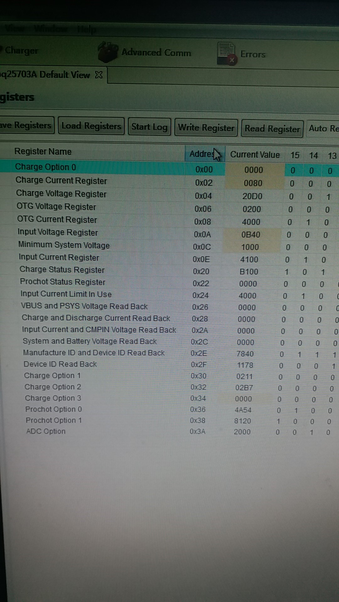
    As shown in the picture, there are many registers of BQ25703A. My question is simple that what can I configure BQ25703A if I 'm a novice engineer.

    1 If I want to change the output current of the chip, which registers must be configured

    2 Or to put it another way, I need a example to understand how to use it. Can you help provide an example of a charging current of 5V 3A?

  • Hey Kun,

    Register 0x0A should be set to a lower value than the input voltage, which is 5V in your case. Currently, with 0x0B40 programmed, the input voltage regulation limit is 6.08V. The InputVoltage register programs the input voltage, VINDPM threshold. The purpose of this feature is to reduce the output power (mostly in the form of charging current) in order to regulate the input power. In this mode, the input voltage will be regulated as opposed to the charging current or system voltage. 

    In your case, you are telling the charger to regulate to 6V on the input, but the actual input voltage is at 5V. Effectively, you're telling the charger pull back as much input power as it takes in order to get VBUS back to 6V, which is impossible. The result is no charging current even though you are programming a value.

    In the simplest form, the charger requires a valid input voltage (above UVLO and below ACOV), a programmed charging voltage, a programmed charging current, and a battery. The IINDPM and VINDPM threshold also need to be programmed appropriately in order to effectively charge.

    Regards,

    Joel H