


Hello:
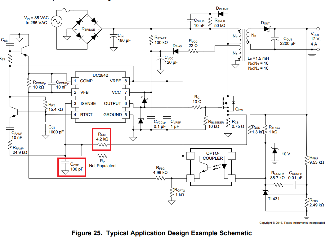
I made a flyback power supply in the same way as the reference circuit of UC3843. The block diagram is similar to the following:
In my actual circuit diagram, Rcsf=1k, Ccsf takes 330uF~1000uF. I found that the power supply had a self-oscillation when the Ccsf took 1000uF. The output ripple is increased from 30mV to 90mV, and the oscillation frequency is about 30kH. When Ccsf takes 330uF, the power supply is normal, the ripple is 30mV, and the frequency is 400kHz. The switching frequency is 400kHz.
I looked at the manual for the Rcsf, Ccsf value description. As shown below:
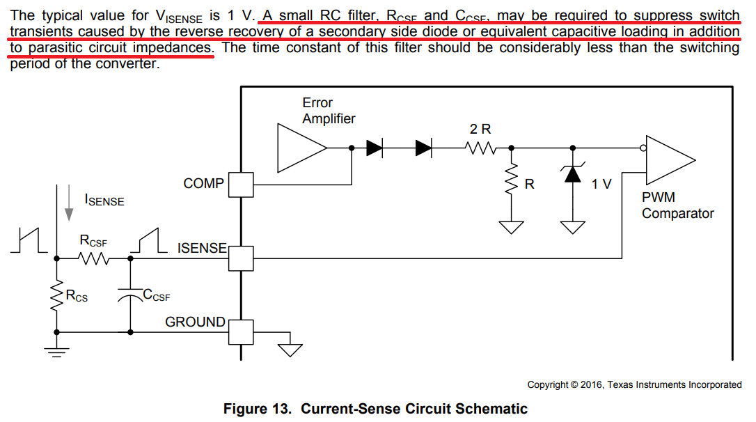
I see the manual only from the perspective of RC filtering, saying that the time constant of RC is less than the switching period.
From this point of view, Ccsf should take 330pF~1000pF to meet the conditions.
It should be the switching frequency fs=400kHz, and the switching period Ts=2.5us.
Rcsf=1k, Ccsf=1000pF, RC time constant t=RcsfCcsf=1us; Rcsf=1k, Ccsf=330pF, RC time constant t=RcsfCcsf=0.33us; all are smaller than the switching period T.
But why does Ccsf take a little bigger and cause self-excitement?
I suspect that Rcsf and Ccsf are actually in the inner loop of the current, which will affect the performance of the current inner loop.
However, I don't know how to quantify the parameters of Rcsf and Ccsf.
The analysis and calculation of the loop compensation parameters in the manual are only the harmonic compensation and the op amp-based compensation parameters.The parameters of Rcsf and Ccsf are not calculated, or Rcsf and Ccsf are not considered in the loop compensation.
However, the value of Ccsf in practice does affect stability. In the flyback power supply I made, Ccsf takes 300pF power supply stable, Ccsf takes 1000pF power supply instability, how can this be analyzed?
In addition to the RC time constant is less than the switching period, are there other restrictions for the parameter design of Rcsf, Ccsf?
Need to consider the current inner loop? How to analyze the calculation of the current inner loop? It feels very complicated. The examples in the manual do not seem to consider the design of the current inner loop compensation parameters.

