This thread has been locked.

If you have a related question, please click the "Ask a related question" button in the top right corner. The newly created question will be automatically linked to this question.

TPS562210A: Output is not generated

Part Number: TPS562210A
Other Parts Discussed in Thread: TPS563210A

Hi

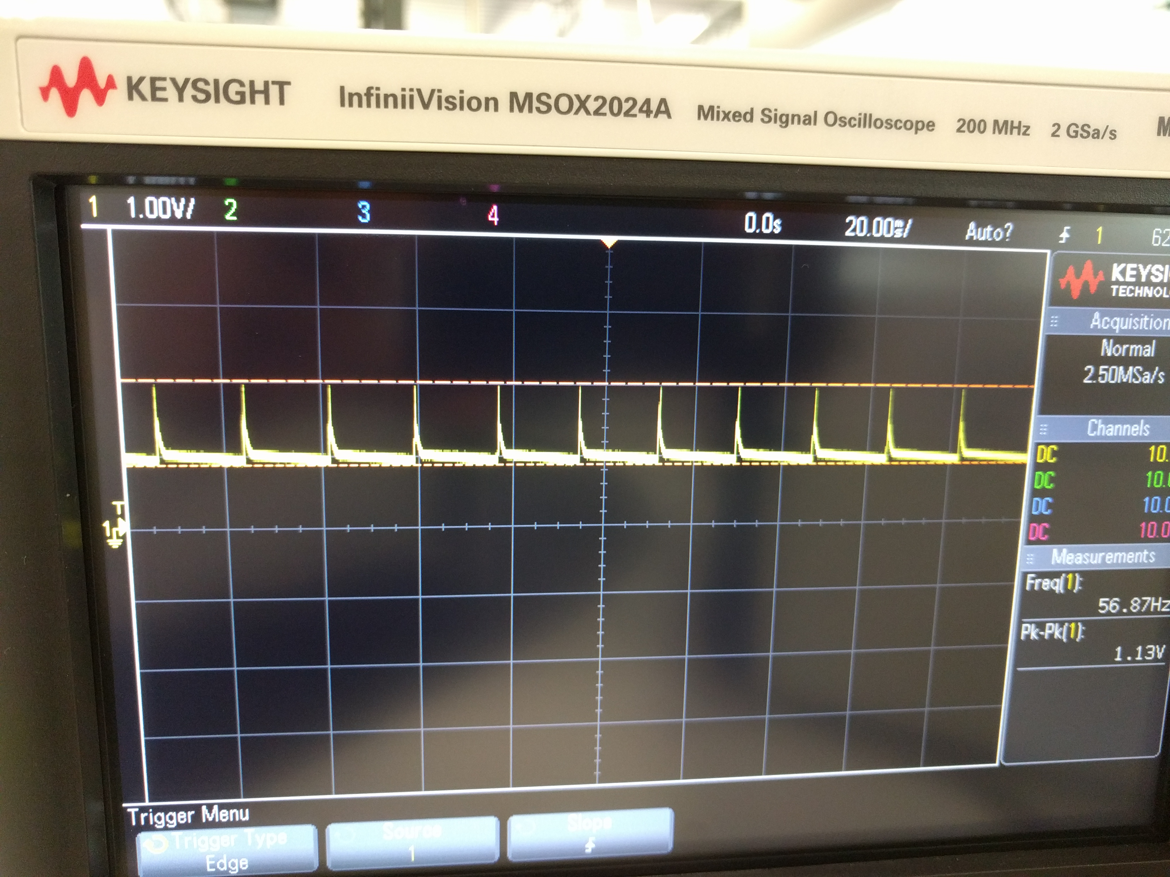
I used the circuit similar to the EVB, to get 5V output voltage, with input voltage 12V. I measured the output voltage on this to be 1V.

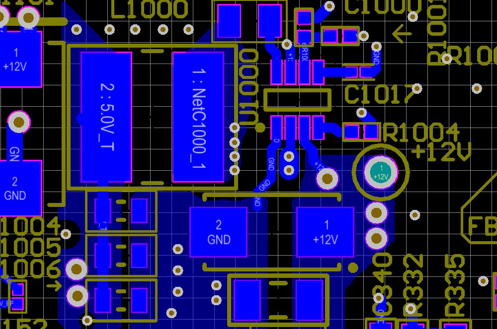
When I try to probe near the VFB resistor (R1000) - just by touching I see a 4.9V output. It observed in all boards. Not sure what is causing this erratic behavior ?

Attached are the schematics and board layout.

I would appreciate your help in this regard.

Venu

  • Hi Venu,

    Did you capture the waveform on SW and is there any other caps on the 5V besides the 66uF showed in the schematic? It is possible that the device is overcurrent and enter into hiccup mode. One way you could try is to increase the value of C1017 to longer the soft start time to avoid the overcurrent protection during soft start. 

  • Hi Anthony

    I Didn't capture the waveforms yet.

    The other circuitry has lot of caps. The overall capacitance is 120uF.

    I did the simulation to see, with 120uF. It is 5v with ss/nr set to 8.2nF.  I could try increasing the cap, to increase the soft start time, it will effect the output ripple value, am I right.

    I will post the captured waveform by end of the day.

    Venu

  • Hi Anthony

    Attached is the waveform, when it is powered up.

  • Hi Venu,

    From your waveform, the device is OC protected and is working under hiccup mode. The device is keeping trying auto restart. 

    Two way to solve this:

    1. Remove C1005 or remove C1005 and 1006 both and try start up again

    2. Enlarge the value of C1017. It will only affect the soft start time and will not impact the output ripple. Thanks!

  • Hi Anthony

    I have checked removing the C1005, C1006. It didnot resolve the issue. The same with the C1017, it didnot effect the output voltage. You are right, the device is over current protected mode.

    I measured the voltages on the Vbst pin which is 6.5Volts, which is incorrect it must be close to Vin. Am I right.

    I am still not sure what is causing it.

    Just to let you know, to see if it issue, I fed the output of this regulator to two LDO regulators (1Dual LDO , 1 single LDO).

    1. Dual LDO is TPS7A880 (Attached is the schematics)

    2. Single output LDO is TPS7A4700RGWR is similar with 10uF and 10uF input capacitor

    Venu

  • HI Venu,

    VBST pin is a floating pin which is 5.5V higher than SW. You will need to use a oscilloscope to check the waveform.

    For the overcurrent issue, I would suggest to remove more output cap to make the total value in half of 120uF. Besides, using smaller value inductor may help.

  • Hi Anthony

    Yes. you are right, VBST is a floating pin with 5.5V greater than SW pin. I removed all the Capacitors (now it is close to 30uF), still no change in the output voltage (doesn't come out of OC mode)

    I will try lowering the inductor value, but i am not sure it will resolve.

    I have two such devices on board, one device works perfectly with no issues (1. TPS562210A followed by LP38798SD, got the expected voltage). The other one with TPS562210A followed by 2 regulators doesn't.  The layout exactly same for both devices.

    The following is the waveform at VBST pin for the faulty device.

    Regards

    Venu

  • Hi Venu,

    If so, the only idea I have left is that your LDO draw too much current at start up. I checked your dual channel and single channel LDO and I found they could output more than 3A current without overcurrent. If adding up the charging current to TPS562210A ouput cap, the device will indeed get into overcurrent protection. The other way to try is to switch TPS562210A to TPS563210A. You will get a higher current limit Thanks!