This thread has been locked.

If you have a related question, please click the "Ask a related question" button in the top right corner. The newly created question will be automatically linked to this question.

BQ34110: Strange results obtained during EOS determination

Part Number: BQ34110

We use the BQ34110 in an application using 3xNiMH cells and are evaluating the EOS determination function. We use the host triggered mode with LSM = 1. A voltage divider is used in the application and the data flash Voltage Divider register is configured (0x15A9). Using the Voltage() and Current() functions correspond to correct voltage and current. The learning load is 39 Ohm. Activating the LEN pin and using Current() gives reasonable results.

However, when performing a EOS determination to get a RCELL reading the results are very strange and far from expected. We get a RCELL of 1949 mOhm and the Learning Start/End Voltages as reported by EOSSTATUS1 are in the order of 18000 mV.

Could there be some configuration missing that could explain this? Expected RCELL is ~100 mOhm and voltages should be in the 3800 mV range.

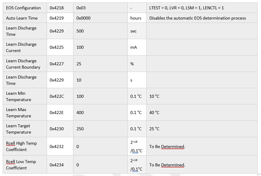
All also wonder where I can find the the spreadsheet that is supposed to be used for calculation the Rcell High & Low Temperature Coefficients based on measurements. For now the coefficients default to 0.

Best regards,

  • EOS determination of Rcell depends on correct mode usage. We advise that once your initial Rcell is learned using LSM=0. Directly, the value of cell resistance learned in DOS determination of Rcell is not relevant, however, the rate of change of it is what matters. If your learning cycle has been completed per the instructions in the TRM, your values should be accurate.

  • We use the BQ34110 on the host side and it is only powered when the host is fully powered. We need to use the host initiated mode and we acknowledge that in our case this means we will need to collect several Learned Resistance values in the host and take decisions in the host. Most likely EOS decision will be based on a RCELL rate of change criterion.


    However, it still seem strange not to get reasonable values? We have not perfected the charging prior to initiation, so the so far learned resistances have some variation due to that but still… Latest run:


    EOSLearnStatus() => 0080 (so LDONE)

    EOSSTATUS1 = 00000000000008474E49000000002E3029005E00C60B (Learning start voltage = 0x474E, Learning Stop Voltage = 0x4900, Avg Current = 0x5E)

    EOSSTATUS2 = 0005 (EOS Learned Resistance = 0x0500 = 1280 mOhm. )


    Surely something must be wrong... Also where to find the spreadsheet for temperature coefficients?


  • Hi Torgny,

    Allow me a few days, I'll try to get a reply back to you in a week. I need to talk to the fw developers to confirm the variance that you are seeing here.

  • Hi Torgny,

    I spoke to the developers, their reply was that you can see a variation if your Rcell computed during chg would be varying then the rate of variance is what matters.

    We don't have a spreadsheet for thermistor selection here. The preferred thermistor for this part is the Semitec 103AT.

  • Hi Batt,

    I think the real issue is not the variance, its that the values obtained are not reasonable at all.

    EOSLearnStatus() => 0080 (so LDONE)

    EOSSTATUS1 = 00000000000008474E49000000002E3029005E00C60B (Learning start voltage = 0x474E, Learning Stop Voltage = 0x4900, Avg Current = 0x5E)

    EOSSTATUS2 = 0005 (EOS Learned Resistance = 0x0500 = 1280 mOhm. )

    This data suggest that the ESR of the battery is at 1280 mOhm. The real value is expected to be more like 100 mOhm! Also the extra EOSSTATUS data about the voltage suggests that something is maybee incorrectly configured because Learning start voltage = 18.254 V and Learning Stop Voltage = 18.688 V are crazy. It is a 3 cell NiMH battery. Using the Voltage() function gives the correct values but the EOS function reports something quite different.

    The second question does not relate to the termistor. Its about how to calculate the temperature coefficients that the EOS algorithm can make use of for compensation of the deviation in RCELL as function of temperature. But I found the Excel sheet in another thread so we leave that for now. Currently coefficients are 0 as per instructions in the TRM.

    Can you ask the developers if there is anything I could have configured incorrectly that would explain the way off voltage readings and RCELL reading during EOS? The data flash Voltage Divider register is configured (0x15A9) and the Voltage() function gives correct readings.

    Best regards,

    /Torgny

  • Hi Torgny,

    Let me talk to the developers again. In the meanwhile, can you please send your srec so that we can look at your settings?

  • Hi Batt,

    I don't have a srec to provide. But these are the dataflash setting I consider relevant for the EOS function ad that I have programmed the device with:

  • Sorry, a typo for Learn Discharge Time 0x4229 should be 500s as this is default (long time though...?)

  • Hi Torgny,

    I checked with the developers. NiMH in EOS can lend itself to errors if the learning load varies, this is because of hysteresis in the battery. One suggestion was to use an average of learned values to monitor the hockey stick type of increase in resistance. Please see if this is possible for you.

  • The plan is to take readings every fourth week or so. So averaging does not seem like a useful solution, but lets disregard the variation.

    The main issue is that values are way off. Resistance is a factor 10 off and the voltage values are a factor 4 off. There must be something else wrong. Ask about the reasons of the EOSSTATUS1 = 00000000000008474E49000000002E3029005E00C60B (Learning start voltage = 0x474E, Learning Stop Voltage = 0x4900, Avg Current = 0x5E) when the actual battery voltage is around 3.8V. As this is crazy, surely any calculation occurring after based on these values will be incorrect as well.

    Regards,

    /Torgny

  • Hi Torgny,

    Please check out these videos for help,  and