This thread has been locked.

If you have a related question, please click the "Ask a related question" button in the top right corner. The newly created question will be automatically linked to this question.

LM5145EVM-HD-20A: Calculation and simulation results are different from loop measurement result

Part Number: LM5145EVM-HD-20A
Other Parts Discussed in Thread: LM5145, LM5145DESIGN-CALC

Hi team,

When I test LM5145 EVM, I feel confused that my calculation and simulation results are different from the loop measurement result. In order to make the simulation closer to reality, I considered the following factors:

1. All components parameters including compensate network are same with EVM.

2. I followed the datasheet and set VRAMP= VIN/kff

3. For the output capacitors, I considered the capacitance variation with different DC bias. I found these data from the capacitor vendor's website.

Below picture shows the calculation, simulation and measurement results.

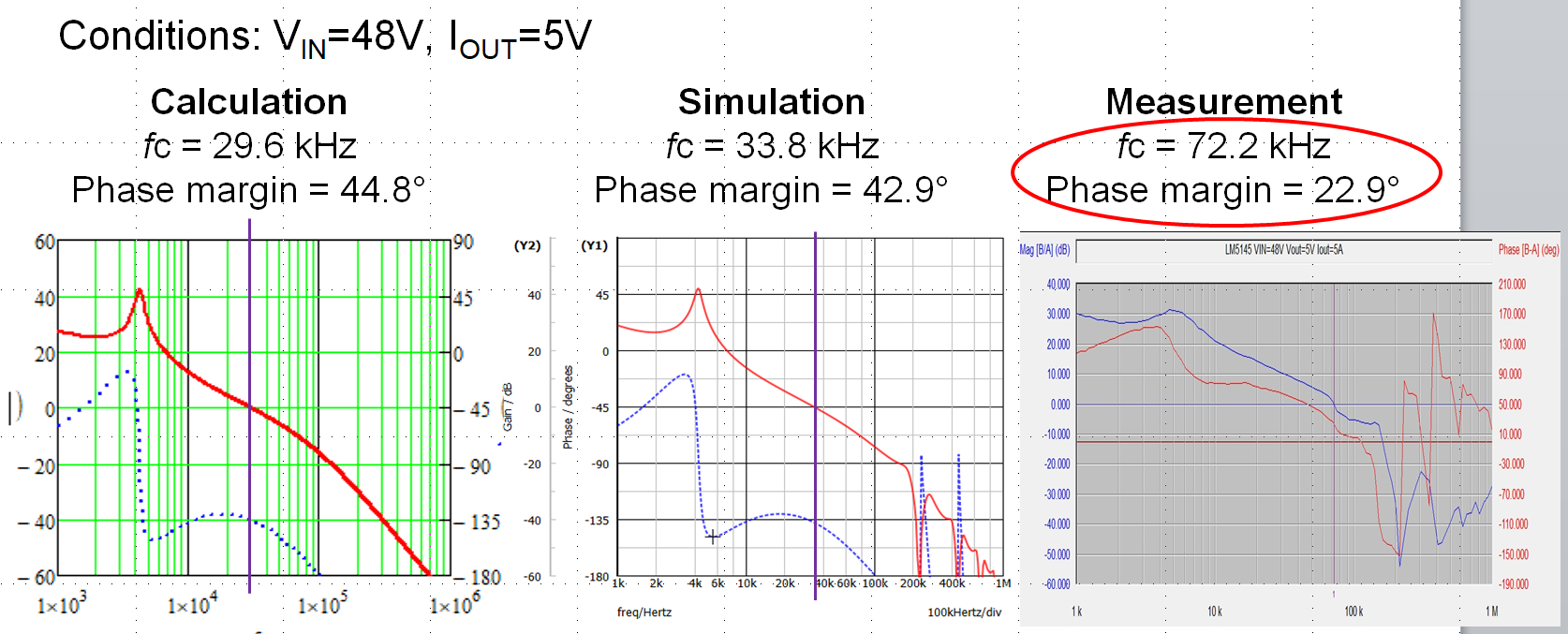
Could you please help to check if there is something wrong with my test results? Do you have any loop gain measurement results of LM5145 for reference?

Look forward to your feed back, thank you.

Arie

  • HI Arie,

    The Fsw of this EVM is 225kHz, and it would be impractical to have a crossover frequency above 20% of Fsw (45kHz). My understanding is that the calculated and simulated plots are correct and there's some issue with the measurement. Also note that the load transient response is quite stable and well damped, indicating a phase margin above 45 degrees.

    Please use the LM5145DESIGN-CALC for further assistance with compensation values and bode plot performance.

    Regards,

    Tim