This thread has been locked.

If you have a related question, please click the "Ask a related question" button in the top right corner. The newly created question will be automatically linked to this question.

UCC21520: Dead time issue

Part Number: UCC21520

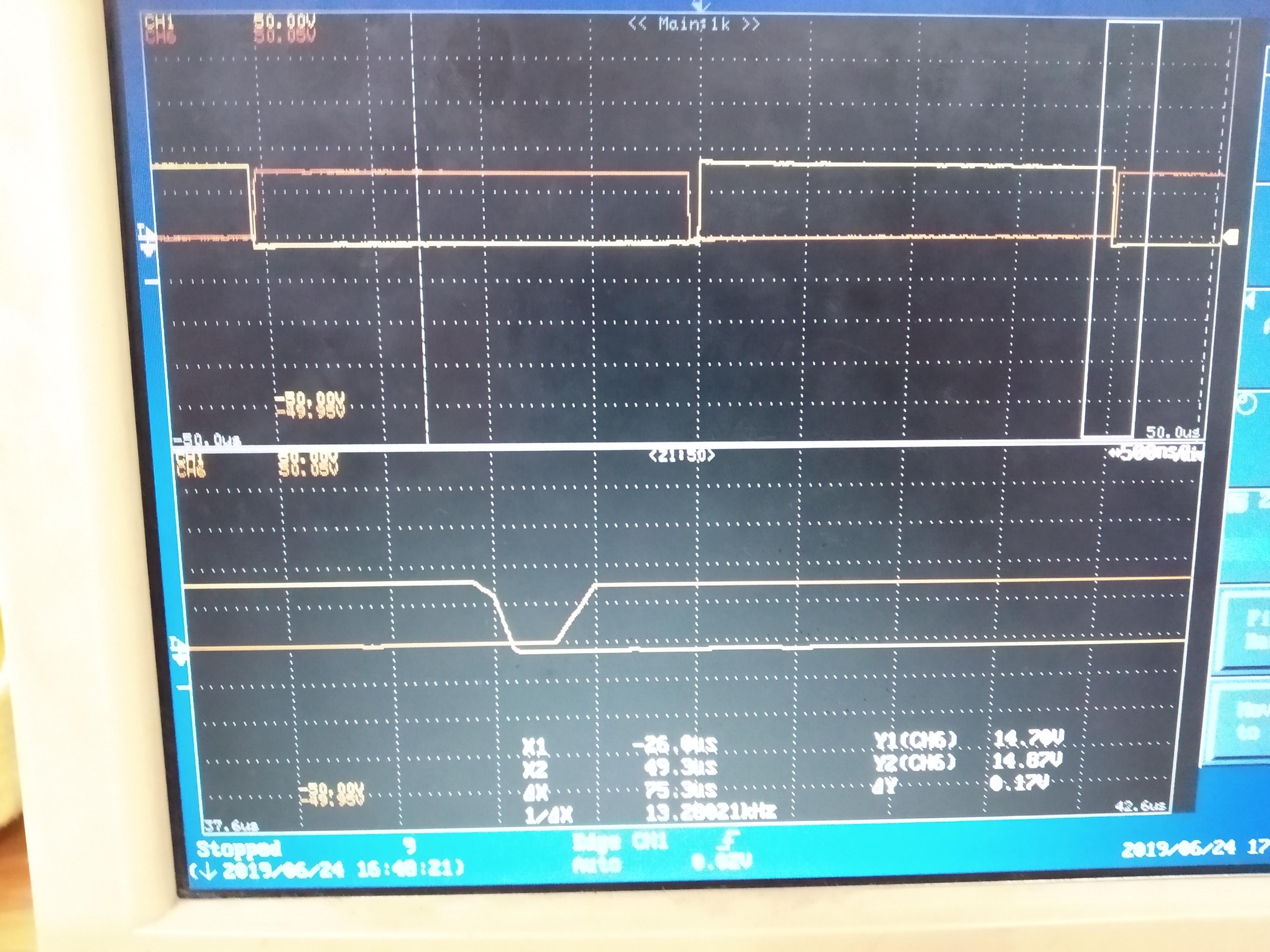
This IC has an adjustable dead time feature and it mentions that the dead time appears when INa and INb go from high to low or vice versa. However, this is not happening. I have connected a 100K resistor at the DT pin and I have connected a 100 nF capacitor across it. I am receiving a waveform in which a dead time of 1 us is observed only when the INa goes from high to low and INb goes from low to high. When the situation is reversed I am not getting the desired dead time. 

I have attached the image that shows the variation of dead time. It is correct for only one case i.e. when the INa goes from high to low and INb goes from low to high. Am I missing something ?

Also I am carrying out this testing at 15 V of VCC, VDDA and VDDB. Also the DC link voltage given when capturing this waveform was 0V.

  • Hi Atharva,

    Thank you for your question. I work on the applications team in the high power drivers group.

    The DT pin can be very sensitive to routing. We recommend keeping the RDT and decoupling capacitor very close to the IC, minimizing the loop area of this circuit. Since this pin tries to regulate itself to 0.8V, is also possible that the 100 nF capacitor is too large. Can you please try something smaller, between 2.2nF and 10nF, and see if that helps this issue?

    If this doesn’t help, could you please share your schematic, layout, and probing configuration, so I can better help diagnose this issue?

    If this answered your question, could you please press the green button? If not, please feel free to ask more questions.

    Thanks and best regards,

    John