A related question is a question created from another question. When the related question is created, it will be automatically linked to the original question.
If you have a related question, please click the "Ask a related question" button in the top right corner. The newly created question will be automatically linked to this question.
Thank you for your question. I work on the applications team in the high power drivers group.
UCC21220 does not have short circuit protection. If the output is shorted to VSS and turned on, this will overheat the device and eventually cause damage. Is there any concern for this short to occur in your system? Normally, if the gate is shorted to the source in any situation, there are larger issues to worry about.
If this answered your question, could you please press the green button? If not, please feel free to ask more questions.
I'm working on a circuit that should behave as pass transistor and current limiter at pretty high voltage ( about 150 V dc ).
In normal operation we expect about 200 mA on our circuit and we want to limit / turn off the switch if current rise over let's say 500 mA.
We put togherter a couple of power mosfet connected back to back and we think to drive them with UCC21220 because we use it in another application and it has two galvanicaly isolated outputs.
Unfortunatelly the way we think to limit current could put a temporary ( 1 -2 us ) low impedance between gate drive outputs in case of fault.
Of course low impednace is not a short but I think that without protection the results will be the same.
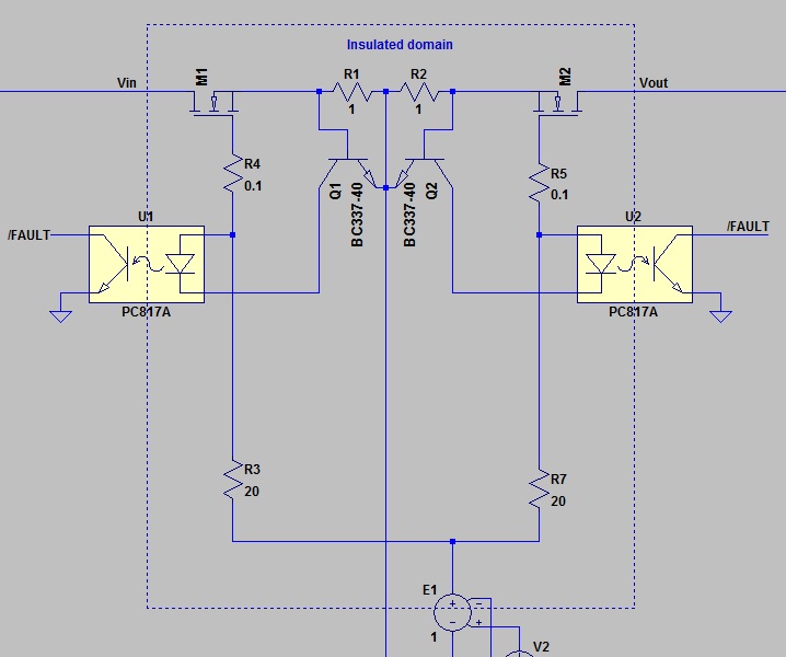
is fairly simple idea; basically we plan to use a standard mosfet current limiter circuit but instead modulate the mosfet we turn on an optocoupler that disable the gate drive.
Here a schematic were E2 could be UCC21220. as you can see if the drop across R1 goes over the Q1 Vbe a current start to flow inside the optocoupler and we can get a signal that switch off the gate drive in less than a us but the current is limited only by the gate resistor. If we want high commutation speed I think i'll we reach value uncompatible with the UCC21220 output.
What do you think ? Is there a most suitable solution to get an high voltage bidirectional switch with us switching time and current limit ?
Thanks for sharing your schematic. I assume you mean E1 could be UCC21220, instead of E2, please correct me if I’m wrong. Is the 1 Ohm the final value? What is the desired current limit fault level? Could you share a bit more of your schematic?
Does the fault signal/current limit need to latch on? Whenever E1 pulls low, it will also stop the flow of current through the opto-coupler, turning the Fault signal low.
What is the value of Vin and Vout? Do you need basic isolation, or just functional isolation?
You might also be interested in our single channel isolated drivers with protections, like the ISO5451. This driver integrates a DESAT protection circuit with integrated fault monitoring output, which could replace the optocouplers and BJTs in your circuit. The DESAT threshold circuit can be level shifted using Zener diodes, and additional resistance in series with the FET drain-source path like R1 and R2.
you're right, E1 represents the UCC21220. The current limit treshold should be around 600 mA so probably we need to increase the sense resistors to 1.2 ohm.
The standard working current is 300 mA max
There isn't too much around that circuit, we have an FPGA that can handle the fault signal and latch it.
Vin is an analog signal with value between 10 to 150 V.
We need only functional isolation for this circuit.
ISO5451 seems nice but is not clear to me how to adjust the treshold.
Is there an application note about the use of ISO5451 with mosfet ?
How precise does the 600 mA current limit need to be? On second look, the DESAT circuit in ISO5451 probably has too much variation (8.3 to 9.5V) to be used as a precise cutoff in this circuit. It would be nice in theory, but I don’t think this driver will work for you. See this thread on adjusting the DESAT threshold.
Looking back at your posted circuit, I think this would work okay, considering the FPGA can maintain the fault flag. You might want to place a current limiting resistor (~100-1k Ohms) in series with each LED in the Optocouplers, in order to prevent them from conducting too much current from UCC21220.
How will the VDD-VSS voltage be generated for UCC21220?
If this answered your question, could you please press the green button? If not, please feel free to ask more questions.