This thread has been locked.

If you have a related question, please click the "Ask a related question" button in the top right corner. The newly created question will be automatically linked to this question.

TPS92691: TPS92691 EVM testing and PWM max duty cycle

Part Number: TPS92691

Dear Sir,

Our customer have design TPS92691 and they currently try using our EVM to modify to their application to earlier testing. and currently they got some question.

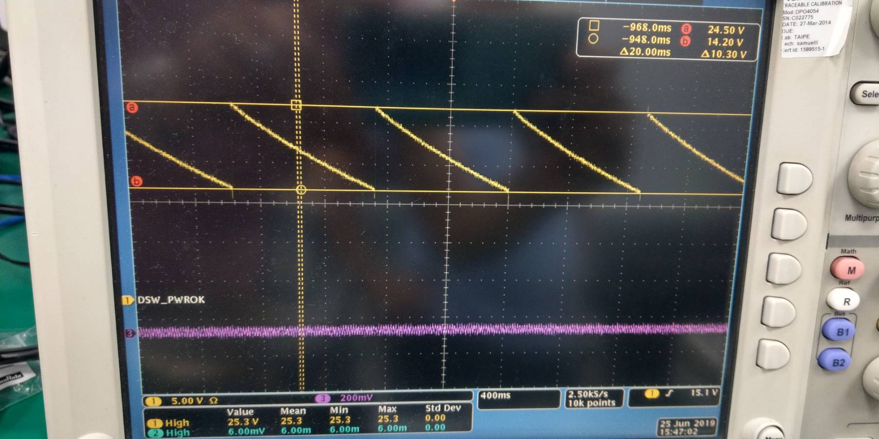
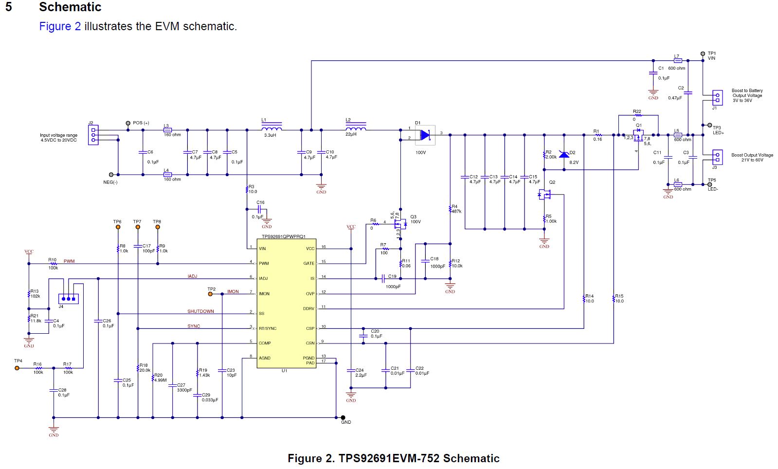
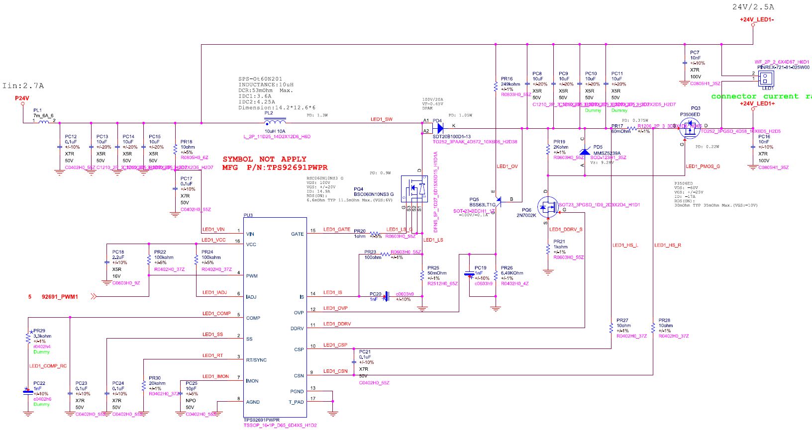
1. They have tried to modify the EVM into their design and it seems having some issue with LED light. Could you kinldy help us check if there is any part that we should be noticed? we have modify about the the part and relation connection to the their design expected PQ5 . please kinldy help us with it .thanks in advance 


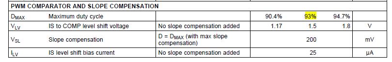
2. PWM max duty cycle 

We notice that for the PWM max duty cycle is only 93%(94.7% max.). But can we be able to use TPS92691 for 24V to 24V 2.5A  LED driver under buck-boost application? Please kindly let us know

Above, if there is any question,please feel free to let me know 

Cheers

Alec

  • Hi Alec,

    Question 1 from above:  What kind of problem are they seeing?  Can you be more descriptive and give us scope capture of what is happening?

    Question 2 from above:  The specification you show is for the internal PWM comparator and slope compensation only.  You can drive 24V to 24V at 2.5A for buck boost configuration full 100% on.   This is high output power and for buck boost the power dissipation on the switching FET can be high so that what you will have to worry about.

    Thanks Tuan

  • ()Dear Sir, 

    Here are ore detail description about customer's issue. 

    They Modify EVM to their their design(as i mention in my previous mail). With their 60W  LED module, the Vout looks a little un-normal shown as below(there is ramp wave on the Vout) . and the LED module is on and off as the ramp wave cycle. And then we lower the Vin to under 22.7V , then the LED module work fully turn on but the Vout still similar to the waveform below

    Please kindly help us check if there is sometime that we are missing or any solution for their issue. thanks in advacne

    any other question, please kindly let me know

    Alec

  • Alec,

    Please have scope capture of what PWM input (pin4), current on the LED with a current probe, GATE ((pin15) and Vout.  One scope capture with all the signal on it.  The timebase should be such that we see 3 PWM pulses and triggering the scope off PWM.

    The TPS92691 is a current controller so it's the current on the LED that you care about.

    Thanks Tuan

  • Dear Tuan,

    Now we could power up and light up the LED 60W module. However, for RD's design is 24V to 24V@2.5A . and currently. we only measure 23.3V Vout. we have tried to adjust the OV to higher set point but it seems no help for the Vout(we have used the same LED module on RD's another design with  TPS92602 . and the Vout can be upto 26V output when we adjust the OV pin setting of TPS92602). Could you kindly give us some suggestion about to improve the Vout to match their design(24V to 24V@2.5A) thanks in advacne

    Cheers

    Alec

  • Alec,

    It's a constant current controller so if the LED forward voltage is 25V it will drive to 25V.  The LED load determine the output voltage not the controller.

    Thanks Tuan

  • Dear Tuan, 

    Thanks for the update and sorry for the later reply. we understand that the LED voltage is decide by the  LED forward voltage(current). However, we use the same LED module on TPS92691 EVM and their own LED light broad which using TPS92602 and the Vout is different, As my previous mail's description, the  design using TPS92602 which can output voltage up to 25V but the TPS92691 EVM can only output 23.3V. RD is questioning if the LED voltage is determined by the LED module, then why there are different LED voltage output between  TPS92602 and TPS92691 design . Is there possible because that one(TPS92602) is using boost structure and the other(TPS92691) is using buck-boost  structure?

    above, please kinldy help us with RD's question and hope to hear from you soon

    Cheers

    Alec 

  • Hi Alec,

    There can be different depending on where your are measuring the output voltage.  Please measure the current on both to see if they are the same.  With the same current  and same temperature the output voltage should be similar.  As current flow the LED will get hot then the LED voltage can change.  Beyond this you will have to trouble-shoot your hardware to figure out the real reason.

  • Hi Alec,

    We have not heard back from you so we believe you may have solved the issue.  The thread will close not but will reopen if you reply.

    Thanks Tuan