This thread has been locked.

If you have a related question, please click the "Ask a related question" button in the top right corner. The newly created question will be automatically linked to this question.

LM5145EVM-HD-20A: Abnormal loop measurement result

Part Number: LM5145EVM-HD-20A

Hi team,

I asked a question before in the below link:

https://e2e.ti.com/support/power-management/f/196/p/813926/3012298#3012298

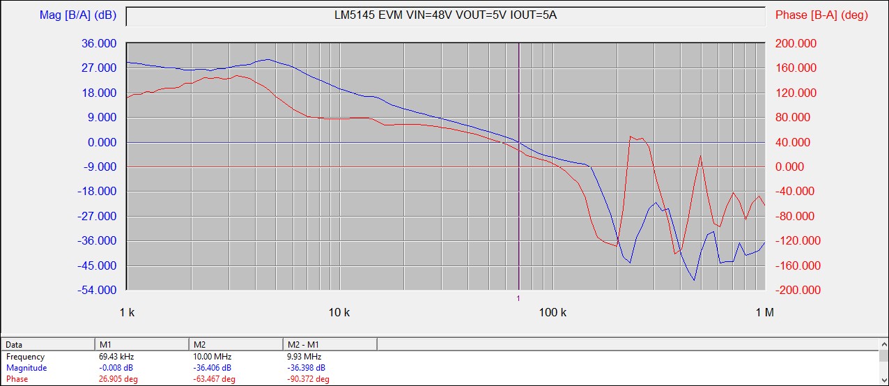
I found the loop measurement results of the EVM is abnormal and different from calculation and simulation. Yesterday I measured three new EVMs again and all of them show the abnormal loop characteristics as I found in last question. I think the measurement method should be right, below picture is my test setup. Is there any possibilities that the components on the EVM are different from the BOM? Could you please help to measure the loop of the EVM to have a check? Sincerely thanks.

Best regards,

Arie

  • Hi Arie,

    If the crossover frequency was actually 70kHz, then the regulator with switching frequency of 225kHz would show some signs of instablity. As mentioned in the previous thread, 20% of Fsw is the theoretical max for setting the crossover. There is an electrolytic cap installed on the output of this EVM that provides rolloff - make sure this is installed.

    You can perform some time domain measurements to check frequency domain behavior:

    Measure the load transient response to see if it is stable and behaving as expected (and also derive the approximate crossover frequency and phase margin from that).

    Measure the SW node voltage to see if it's stable with no jitter.

    Regards,

    Tim

  • Hi Tim,

    Thank you for your reply. The electrolytic cap (C13) is installed.

    Below is the load transient waveform I measured before. There is an obvious ringing of Vout. Can the waveform show that the phase margin is too small? How to derive the approximate crossover frequency and phase margin from the waveform? Thanks a lot.

    Best Regards,

    Arie

  • Arie,

    Check the LC tank frequency - does it look higher than expected? If so, that electrolytic might be damaged. Also, you can measure the COMP-to-VOUT and VOUT-to-COMP transfer functions separately to get more detail on the overall behavior.

    See attached article.

    808PET22-eliminate-crossover-frequency-guesswork.pdf

    Regards,

    Tim

  • Hi Tim,

    Thanks for this article. I don' think the electrolytic cap is damaged because the LC resonant frequency looks the same with calculation. Meanwhile, I used three EVMs to measure the loop behavior and they are all the same, so the possibility of electrolytic damage is low. To figure out the reasons, I will measure the COMP-to-VOUT and VOUT-to-COMP transfer functions separately in the next days. I would appreciate it if you could provide more information for reference. Are there any other reasons that caused this issue? Do you have any loop measurement results of this EVM? Thanks a lot.

    Best regards,

    Arie

  • Hi Arie,

    I will check on the loop measurements. Note that the quickstart calculator online is setup for the EVM (it assumes the effective output cap is 350uF with 4mOhm ESR (this includes the derating of the ceramic cap with applied voltage). Also, the grounds of the probes should be taken at AGND, not PGND.

    Regards,

    Tim

  • Arie,

    It looks like the gain is quite high even before the LC rolloff -- can you check the value of resistor R9 that sets the midband gain (it should be 10k).

    Also, I recommend adding an input electrolytic capacitor to provide some damping such that the input filter does not affect the stability measurement.

    --

    Tim

  • Hi Tim,

    I measured R9 and it is 10k.

    Arie