A related question is a question created from another question. When the related question is created, it will be automatically linked to the original question.
If you have a related question, please click the "Ask a related question" button in the top right corner. The newly created question will be automatically linked to this question.
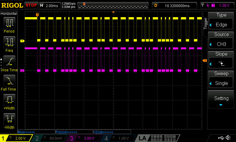
Are there issue with this devices I2C? It doesn't seem to like to share the bus with anything and I can't get it to respond. I have multiple other I2C devices on the bus, LM75, M24C128, ImageSensor, but the LM3370 is creating issues. The s/w is always trying to send restart signals, so to speak, and always sends out repeat restart signals on the bus that never cease. The SCL and SDA signals mimic each other. (see attachment) Then when I remove it from the bus, and put the LM75,M24C128, Image Sensor on bus, I can see the I2C address sent out.
I'm using the LM3370SD-3021 (1.2 and 3.3V outputs). And need to program both the rails for 1.5V and 2.1V. I have re-soldered a new chip onto the eval board twice, but no luck. I'm very very experienced at soldering under a microscope both BGA and 100pin dual row heat slugged quad flat packages, and am confident my solder connections are good because I see the solder has wicked nicely to the pins and nothing is shorted out.
My s/w specialist can't understand why when LM3370 is on bus we have so much trouble, and we've rewritten code and looked at microcontroller registers to see that the LM3370 seems to create a BUSY event. So it keeps trying. The fact that I can connect LM75, M24C128, Image sensor to the bus and not have this issue has prompted me to inquire about the LM3370. I know the device is old, but it is a great device at a super price point!
0x42 is the address I send out but actually can't see that code when LM3370 is on the bus. I can see that code when I connect any of the other fore-mentioned devices on the bus.
I'm 10 miles from the TI sight in Sunnyvale, CA and used to be a power applications engineer for NSC long time ago.
I don't know of any specific issues. Our group inherited support for LM3370 via a re-org. This is the first instance of support for it. I would probably need to order hardware to try to duplicate your issue. Are you using the
AN-1840 USB I2C Interface Board
to interface to your LM3370? Or some other interface?
I'm using the AN-1428 LM3370 Eval Board. Probably the very last eval board ever given out. The saleman I new was somehow able to drum one up a few years ago, and I think it came out of the lab or was sitting in someone's desk. I didn't know AN-1840 existed. That would be a good tool to interface to the board, and quickly see if the board I have is ok, and of course the solder joints good too. After resoldering the LM3370SD-3021 to the board the 1.2 and 3.3V rails are good and of course the switch node too. There's just 2 lines left, and I can visually see them under microscope and follow them to the solder wicked up pins.
I don't know if you are local in Sunnyvale. I'd be willing to come to your lobby to pick one up. Having used these kind of boards before. I've just been burning too much time trying to get over this issue.
Unfortunate thing is that last year it seemed the interface worked. But know I'm starting to doubt that was really the case.
Neither toggling power hard wire disconnect wise, nor toggling of enable pin, codewise or hard wire disconnect wise helped. Thanks for the suggestion. Hopefully, you'll be able to get an eval board and try some other things. Thanks, Angelo
It appears that the eval board has been obsoleted. It would technically be possible to recreate it, but it would require a strong business case and at best would take a couple months. That probably does not help your situation.
About all I can recommend at this point is to take it slow. I think you said that everything works as expected with only the master and LM3370 connected correct?
That is incorrect. The LM3370's I2C bus doesn't work at all. Any time I put it on the bus, it makes the bus inoperable. I have LM75, M24C128, and an Image Sensor that respond, but not the LM3370. It's very frustrating. I've done a ton of work on this, and I'm no slouch when it comes to working with specialists and doing a lot of specialized work on my own. Any chance of sending me that USB interface board?
I don't know how what else to do. I've replaced the IC twice and both times switch nodes are perfect and outputs are exactly as default. I can't look much more at 2 lines under a microscope that already show a perfect solder wick to the IC's SDA, and SCL pins. And they aren't shorted together.
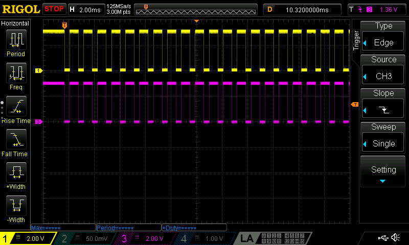
LM75 on bus alone not even powered: I2C master sends 0x42.
M24C128 on bus alone not even powered: I2C master sends 0x42.
Image sensor on bus alone not even powered: I2C master sends 0x42.
No integrated circuit on bus: I2C master sends 0x42.
LM3370 on bus alone not even powered: I2C master does the repeat restart so to speak (the SDA and SCL look identical, but they aren't shorted).
I did more microscope visual and ohm-meter poking around on the LM3370 eval board since it is quite old and visibly so. Using a very very fine probe and a microscope of ~40X power or higher (enough magnification to see the wicking and a fine probe very very clearly touch just the upper section of the wick), the bus is definitely connecting to the SDA and SCL pins solder wicked. This fine probe is really only touching the wicked portion of the pin. Pin 10 and 11 are definitely connected to the bus! I probed VDD (pin 4) and it is definitely at the same potential as Vin1 and Vin2. SGND (pin 5) is definitely shorted to the other grounds on the IC (PGND1 and PGND2).
I thought about toggling the nPOR1 and nPOR2 pins, but decided not to bother. They've never been connected even when I had success a year ago, and block diagram shows they only affect the Bucks, not the bus.
I didn't probe any of the other pins because the switcher has been working and powering up to default voltages 1.2V & 3.3V. EN1 and EN2 work nicely too. I think something is wrong with the EN_I2C inside the I2C Registers EPROM. Or the EPROM has some how been programmed wrong. I remember having to program the internal EPROM of a Summit Micro power IC, to give me diagnostic information (something like that). We could do it a half a dozen times before we couldn't change it anymore. The designer had to give us a special procedure to access it. Maybe that part of the recipe has been lost and the internal address is no able to respond to 0x42 or 0x43?
I don't suppose 10kunits a year is a big enough business case, even though we all know how popular porch camera's have become these days! This is a great chip when the digital control works.
OK thanks. Remember I said that with only the LM75 and M24C128 on the bus, with no power, I can see 0x42 sent on it. And of course with the bus floating with no peripherals connected also allows the master to send the 0x42.
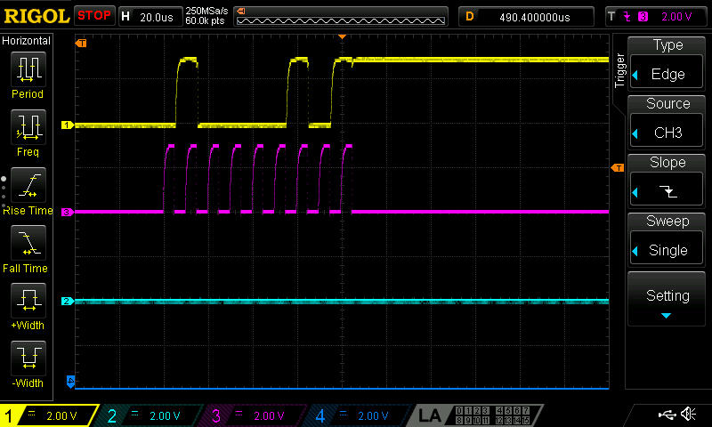
Anyway, I soldered a dead bug (upside down) of LM3370 with only the SDA and SCL lines coming out. Same results: the master doesn't send the 0x42 onto the bus. But it doesn't give me that repetitive repeat "retry" signal, being identical on both lines of the bus, either. Why the dead bug: I did this because the LM3370 eval board is old and not in good shaped, and because a dead bug is easier to see solder joints and really breaks it down to the most basic. And why "unpowered": it just allowed me to swap little eval boards on and off of the bus quickly because no Vdd and Gnd to connect. Clearly, not a conventional methodology, but kind of clearly eliminates the whole idea that the part needs to be reset. Well at least because all the working I2C chips don't need to be powered up to see the master send the 0x42. Anyway, when I either remove the SDA line or the SCL line of the LM3370 from the bus, the master sends the 0x42.
These are really the only new learnings from the dead bug effort:
1) no repetitive repeat at all even when "unpowered".
2) Removing either of LM3370's SDA or SCL from bus allows master to send 0x42.
I had to do this because breaking things down to the basics helps build confidence. I did a dead bug on a 63 BGA image sensor in the past. Soldered down about 20-30 of the 63 balls by hand, under a microscope, in a hand made jig, and all VERY time consuming. The learning there was to break down to the basic, ie eliminate the flex board. It was a risk, but it taught me a lot. Eventually learned a heat plate solder technique to get the image sensor soldered down onto flex circuit just right, but that was all real hard effort and time consuming.