This thread has been locked.

If you have a related question, please click the "Ask a related question" button in the top right corner. The newly created question will be automatically linked to this question.

UCC2803: Faults detected during Startup

Part Number: UCC2803

Hello,

I am using UCC2803 for a dual-output active-clamp flyback converter switching at 1MHz. The input range is 7 V to 28 V and the output is 24 V. Everything was fine except for the startup performance.

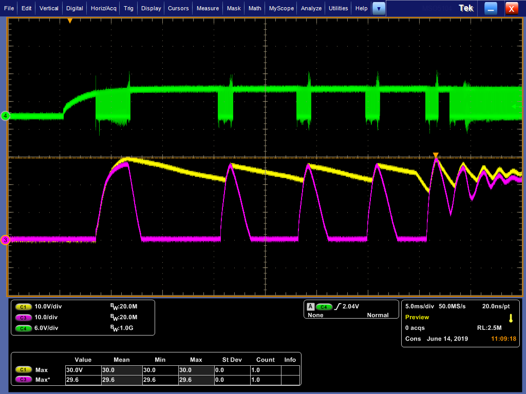
Please see the experimental waveforms during the startup as following. The green waveform is the inverted PWM output while the yellow and pink waveforms are the two outputs of the active-clamp flyback converter. You can tell from the waveforms that the converter successfully entered the steady state in the beginning, however, the PWM output was turned off and turned as the over-current protection was triggered. It repeated several times and this happened randomly. To solve this problem, I reduced the sensing resistor significantly so that the sensed current will be much smaller. It did improve this performance but it could not solve this issue. 

It doesn't make sense to me as it happened after the converter has entered the steady state. Normally the current spike should be smaller than that during the start up and why the faults were only triggered in this period instead of the start up. So I am wondering if TI engineers know what happened and what cause this problem. What can I do to control this.

Thanks,

Jiewen

  • Hello Jiewen,

    The waveforms dont make a whole lot of sense without the schematic.

    Please attach a pdf of your schematic.

    Regards

    John

  • Hello Jiewen

    I think that you are correct that the controller is running into current limit and this is the reason for the on/off behaviour.

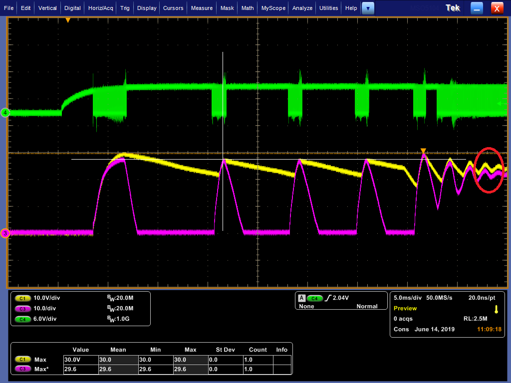
    One thing which is interesting is that the output voltage appears to be very poorly damped when the current limiting behaviour eventually stops - red circle. I'd guess that this indicates a control loop phase margin of less than 20 degrees. It looks as if the output voltage is overshooting its intended level and this is leading to the over current condition. The overshoot may be due to the poor transient response of the control loop. Reducing the amplitude of the current sensing signal helps because that makes the controller less likely to go into OCP but I think that the underlying cause is the loop phase margin.

    I'd recommend that you check the loop stability first - the easiest way to do this is to get the PSU operating correctly in the steady state - like it is at the extreme right hand edge of your screenshot and then apply a load transient while monitoring Vout. Normally a 25% to 75% to 25% load step works well but a 80% to 90% to 80% transient would be ok too - except that the amplitude of the response would be less. Make sure that the load step happens quickly - I'd suggest you have the load change in less than about 100us. Keep the load at each level for long enough for the transient to die away - maybe about 20ms in your case.

    Please post the result here and I can give you some further advice.

    Regards

    Colin

  • Hello Jiewen

    I's been a while since this thread was updated so I'm going to close it now but please feel free to open a new one if there are any further questions about this or any other project.

    Regards
    Colin