This thread has been locked.

If you have a related question, please click the "Ask a related question" button in the top right corner. The newly created question will be automatically linked to this question.

TPS5450: TPS5450

Part Number: TPS5450

Hello,

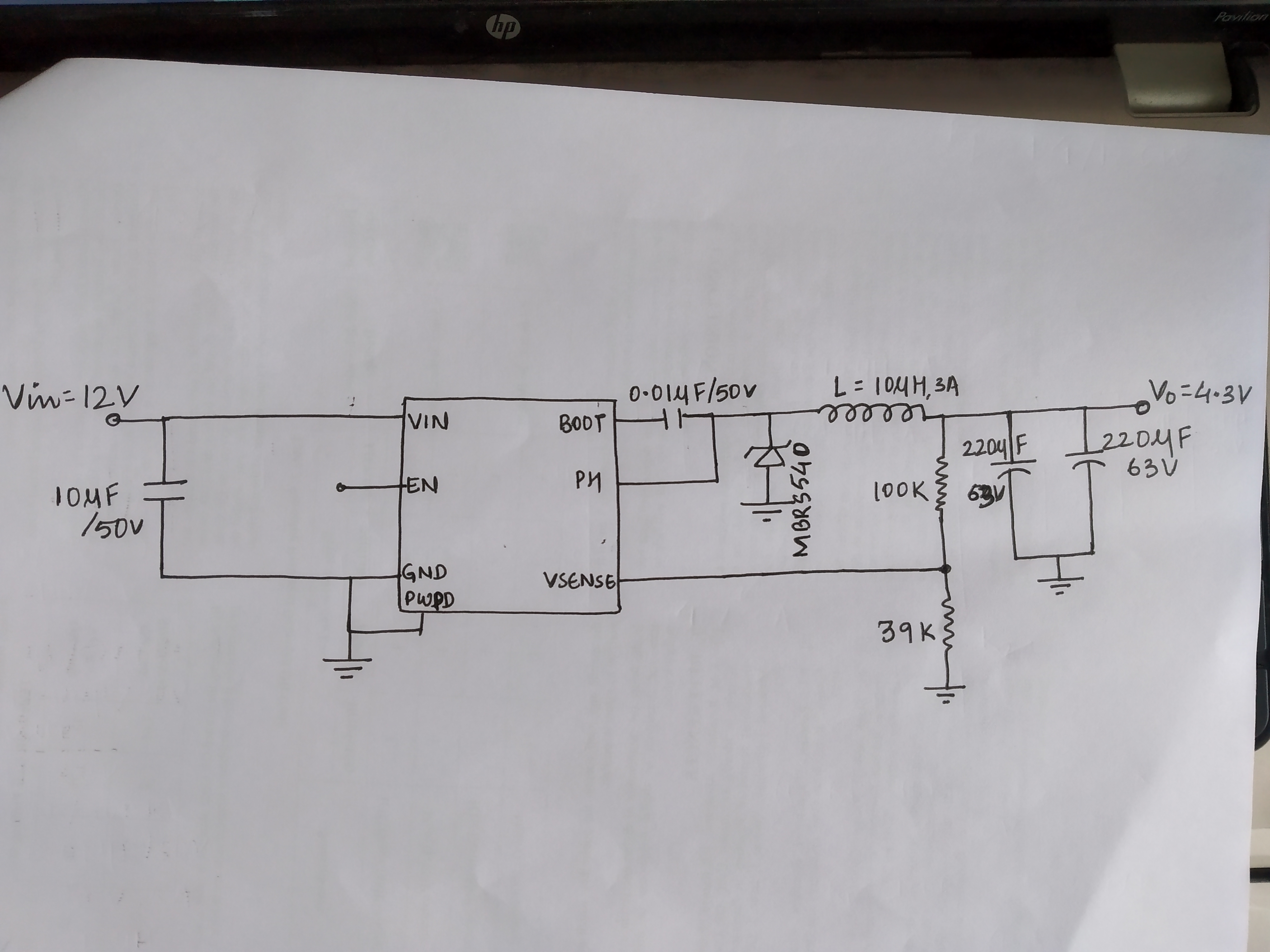
Iam using TPS5450,According to circuit diagram from datasheet there are resistor divider network of r1=10 k and r2=3.16 k, but in my case i use r2 =3.3 k as 3.16 k is not available. following are the observation

vin vout vsense(pin no 4)
5.5 3.6 0.98
6 4.08 1.10
7 5.02 1.36
12 2.92 0.80

when i apply input voltage 12 v or after 11v output voltage is decreasing, and after 12 v it remain contant 2.92 V.

and my requirement is vin =24v, vout= 4.2v and current =3.5A.

Please guide me how to achieve that.

regards

Ajitem Kudtarkar

  • Hi Ajitem,

    The VSENSE voltage should be a constant 1.21V according to page 5 of the datasheet, and the output should be at a defined setpoint based on the values of the feedback resistor divider.

    Please use WEBENCH to assist with component selection. If there's still an issue, you can forward the layout for review.

    Regards,

    Tim

  • hello tim,

    My problem is that, when input voltage is till 10 then output voltage is 5v, after increasing the voltage till 24 output votlage remains constant to 2.9v.

    how to resolve this because in my circuit iam going to give 24v as an input.

  • Hi Ajitem,

    Why is the VENSE voltage not constant here? Please send the layout for review. In particular, the feedback resistors should be located close to the VSENSE pin and the trace to VSENSE should be as short as possible and routed away from noise sources such as the inductor.

    Regards,

    Tim

  • Hello,

    Thanks for your reply. 
    Please find attach images of circuit board which we have made. We have given input 12v and we are getting output 4.3 v without any load provided.
    Following are the observation we observe:
    1. When we increase input voltage gradually from power supply start with 5.5v till 6v, output is constant. when input reaches 6v, power supply getting short and we cant increase input voltage.
    2. When we give direct 12 v input without connecting any load at that time circuit works fine , when we connect load again power supply get short and drop down to 5.2 v.
    Kindly help.
    Thanks 
  • Hi Ajitem,

    I'm not sure where the feedback resistors are positioned in your breadboard, but they should be adjacent the VSENSE pin (such that the VSENSE trace is as short as possible). It would be much better to use the TPS5450 EVM to check operation of this circuit.

    Also, the ESR of these output caps (220uF/63V) is probably excessive, causing a low-frequency ESR zero. I recommend installing ceramic output capacitors (e.g. 47uF/10V) that have inherently low ESR or a low-voltage electrolytic cap with reasonable ESR value (< 20mOhm). See section 8.2.2.6 of the TPS5450 datasheet for more detail.

    Regards,

    Tim