This thread has been locked.

If you have a related question, please click the "Ask a related question" button in the top right corner. The newly created question will be automatically linked to this question.

AutoSwitching Power Mux TSP2115ADRB - Failing

Hi,

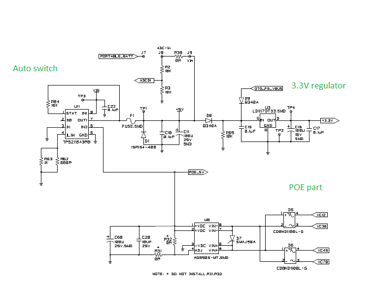
We have used IC TSP2115ADRB, for power switching between main power supply and POE at +5V. The load current is 300mA only.

The IC is failing for some reason, works fine for some.

Please advice any body is facing same problem or any possible solution.

  • Hello Abdul,

    I assume you mean the TPS2115ADRB.

    Can you please describe the failure? Do you mean the device breaks or the MUX is not switching? 

    Could you also let us know, by way of schematic how all the pins of the device are connected.

  • Greetings,


    Thanks for your quick response.


    The Mux is not working, The failure observed in two ways.


    1. IN1 output drop by 1.4V for 300mA current, IN2 continues to give out 5V with 10mV drop (without IN1 connected).
    2. Both IN1 and IN2 fails and IC starts drawing more than 100mA and gets heated up output is not enough for the board to work.


    The part of schematic is attached, revert back for further information.


    We have purchased Qty 50 ea, through our Boston office in US.


    Its being used in product which is at pre production test stage.


    Please support to resolve the problem. Thanks.


    With Regards,

    Abdul Rasheed

  • Abdul,

    Just to confirm my understanding of your issue, you are seeing a voltage drop of 1.4V across the power mux from IN1 to OUT with 300mA flowing through this channel. This heats up the device and causes a failure in IN2 as well. Is this correct?

    I have a few questions:

    1. Out of the 50 units, how many are being damaged?
    2. What is the sequence of events that lead to the failure? Does the issue occur during startup, or DC conditions?
    3. Are there any oscilloscope shots that you can provide us?
    4. Can you try removing your downstream load (perhaps F1) and seeing if the device fails?
    5. Can you remove IN2 and run the device only from IN1 with no downstream load and check if the device fails?

  • Greetings,

    Please find response against each point.

    Yes, your under stand correct.

    I have a few questions:

    1. 7 Ics got damaged, such high failure rate is not usual for ICs.
    2. We have under standing, when IN1 applied from Hameg power supply it damages. We were trying both power supply and removing one. It worked for atleast 5 such cycles.
    3. Saw surge of 6.3V in no load condition, i can provide you oscilloscope screen tomorrow.
    4. We did try by assembling just the TPS2115ADRB IC circuit with resistive load, two ic failed in this set up, one IC failed on applying IN1 without load resistor
    5. Above step was tried with just IN1

  • Hello Abdul,

    Thanks for your quick reply. I will look into this some more. I am very interested in the oscilloscope captures.

    Please note that responses may be delayed over the next few days because of the 4th of July.

  • Hello Abdul,

    Are you still having this issue? I will close this thread but feel free to respond and it will be re-opened. 

    We are waiting on your oscilloscope captures to further understand your issue.

  • We figured out the problem and found solution.

    For benefit of users of this forum.

    We added 100uf capacitor at IN1 pin, earlier it was 0.1uf only. This resolved the failure.

  • Thank you for choosing TI power switches. If you have any more questions, feel free to post on E2E or send a support email.