This thread has been locked.

If you have a related question, please click the "Ask a related question" button in the top right corner. The newly created question will be automatically linked to this question.

TPS40210 : External sync timing requirements

Other Parts Discussed in Thread: TPS40210

Hi team,

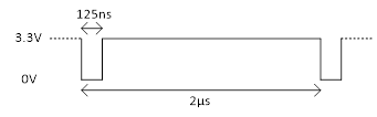
Is there any timing requirement when the TPS40210 is used with the external clock sync  ?

Normally, there should be specifications for the pulldown/pullup pulse minimum timing.

Thanks in advance for your support.

Regards,

Pol

  • Hi Pol,

    experts supporting this device is out of office. they will reply you next week.

  • Hi Pol,

    Thank you for considering the TPS40210.  In the datasheet the requirement for the external sync signal is discussed. Please refer to Section 7.3.6 for details. 

    Thanks,

    Youhao Xi, Applications Engineering 

  • Hi Youhao,

    I'm a bit confused reading the Section 7.3.6.

    I understood we need to add a diode when the duty cycle is less than 50%.

    The customer use case is Fsync=500kHz and a pulse width (pulled low) = 125ns.

    Does it work?

    thanks in advance for your clarification

  • Hi Pol,

    I don't think this works with Figure 23.  If  you can get an inverted signal, go with Figure 24.

    The datasheet reads that "if the RC pin is held low for an excessive amount of time, erratic operation may occur."  Since the sync clock has much wider duty cycle, you should put an RC at the synchronization FET gate:  R is placed from the gate to gnd, and C is between the sync clock signal and the gate.  This will convert signal into small pulses.  The datasheet recommends: Typical values for the resistor and capacitor are 220 pF and 1 kΩ.

    Hope this clarifies.

    Thanks,

    Youhao