This thread has been locked.

If you have a related question, please click the "Ask a related question" button in the top right corner. The newly created question will be automatically linked to this question.

TPS62810-Q1: Redundant 1V Supply?

Part Number: TPS62810-Q1

I'm working on implementing a series of redundant supplies for a safety critical application.  Ultimately, I'd like each individual rail to be OR'ed but at the low voltages some of the cores need this seems difficult using the standard TI ideal diode controllers/efuse products.  

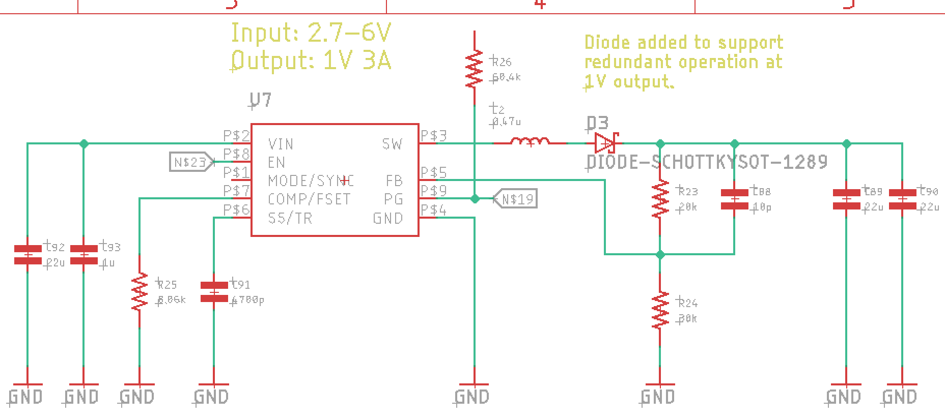
For these low voltage rails, my current plan is to add a diode in series with the inductor of the TPS62810 that I plan to use to power these rails (see below schematic).  This way the switcher regulates the output past the diode, such that the changing forward voltage of the diode with load is accounted for.

My question is will this work?  I can deal with the added power burn of the diode, but I worry about stability and interaction with the second redundant converter.  How would a TI power management expert suggest implementing redundant 1V supplies that drove the same net?

Thanks!

Trey

  • Hi Trey,

    I'm not very clear about your purpose of adding diodes, for reverse protect or other, could you please help explain it ? But I am sure that the output is stable in this case.

    Best Regards,

    Kevin

    If this answers your question, Please click "This resolved my issue" button.
    ____________________________________________
    TPS62810-Q1 – New Automotive 6Vin, 2.25MHz buck family with 1% accuracy and SYNC-pin. 1-2-3-4A options.
    Smallest 2x3QFN package with wettable-flanks for optical PCB inspection.

  • Kevin,

    Thanks for your insight.  Yes, I am looking to protect against reverse bias situations.

    The full implementation will have two TPS62810 supplies with diodes that drive the same 1V net.  The diode is there in case one of the TPS62810 fails short to ground.  I don't care if they share current during normal operation because each supply will be large enough to drive the entire load on its own.

    Given the above, do you see any potential problems?

    Best,

    Trey

  • Hi Trey,

    in general, I think this configuration can work although I did not test is with this device.

    But you should not keep the MODE pin unconnected. For this configuration the only option is to operate the device in power save mode enabled. In forced PWM or synchronized to an external clock it is important to allow reverse current through the inductor. 

    Best regards,

    Juergen

  • Juergen,

    So we would want the mode pin tied low, correct?

    Trey

  • Of course, this is how it is described in the datasheet.