This thread has been locked.

If you have a related question, please click the "Ask a related question" button in the top right corner. The newly created question will be automatically linked to this question.

TPS3701 Wired-Or configuration for bipolar power supply

Other Parts Discussed in Thread: TPS3701

Hello dear Ti community.
I've got some questions regarding TPS3701.

I'm going to use it as a wired-or config for monitoring bipolar power supply (which is +/-24V in my case).

Question is, if I'm going to pull up those outputs with 5V and there will be two ICs (one of them for positive and one for negative rail) how should I connect all four outputs to get it working fine?
I'm asking because negative sensing variant require two resistors and one diode to work - should I connect additional outputs here (red dot on my picture) or for additional outputs (from positive sensing) should I use another pull up resistor and then I could tie all outputs together?


I just want to sense both voltages in my power supply to turn on/off LDO's/DC-DC and when one rail fail I just want to to turn off everything.

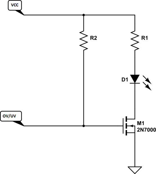
Another question regarding same application is how to drive some LED's to get visual information when there is [no] failure - in this case I just want one LED that will either shine or be turned off when something unusual happen. Because I'm little unsure about it I don't want to add anything that could false trigger or glitch anything.

Thank you for helping me, have a nice day :)


  • Hi Mateusz 

    My understanding of problem statement is - 

    * You have to monitor 2 power rail (+25V and -25V). You want it to be within the window (Let's say 14V to 16V).

    * To monitor negative rail you are using diode so at the red dot point you will get rail of (- {diode drop} to 5V).

    * Can you short output of +ve rail monitoring supervisor on Red dot point? Where can you put LED? 

    My comment is as follow 

    * You can short the other supervisor's (used to monitor  +ve rail) output at the red point in the diagram and use pull up resistor Rpa for all of them.

    * Make sure that potential at red point is not going bellow the absolute max (-0.3V) of the output pin. Otherwise ESD diode will turn on on you may face latch-up problem. 

    * You should take care of Iout current for negative rail monitoring supervisor while selecting Rpb . 

    You can put a LED (with an appropriate  series resistor) from RPU supply to RED dot point. But it will increase the output current. You have to take care of that.

    Please let me know if there is any concern.

    Regards

    Trailokya

  • Thank you for helping me ;)
    My window for monitoring will be different but that doesn't matter here ;)

    How about diode? Should I use something specific, or typical 1N4148 will be sufficient?
    Next question if I'm going to use RPU within 50-100k range I assume that Rpb could be the same value here?

    How about adding some mosfet (like 2N7000 or 2N7002) to drive LED indicator from OV/UV output?
    Something like here :

  • Mateusz 

    The forward voltage of the diode should be less than 0.3V. Other wise you may face latch up problem as mentioned above.

    Selection of Rpb will depend on -Vss value. Make sure that RESET pin is not taking more than 10mA current. That will be calculated as 

        (VSS - VFB)/ Rpb.

    You can directly connect R1 + D1 to red dot point. When any of the o/p will go low, the LED will turn ON (Because it will get a path ).

    Regards

    Trailokya

  • Thank you ;)

    Are you suggesting me that using mosfet is not recommended or just not needed?
    Would you be so kindly to tell me what should I omit M1.

    I'm going to use that OV/UV signal to control startup of LDO's and DC-DC which are sinking very small currents after all.

    If this is important I'll try to use 2mA LEDs.

  • Mosfet is not needed. You can connect it to the diode pin itself. Max output current is 10 mA, which will be current through Rpb + LED current. Hence you can design your system accordingly. 

  •  


    This circuit will monitor both positive and negative rail and give 0V o/p when any of the rail is going out of the window.

    Explanation -

    Case 1 – When both the supplies are within the window -

     In this case all the o/p MOS will be in off state and there will be no current (leakage only) R4 , R5 & R6 resistor. The diode will be in off state.   So the o/p voltage will be equal to VPU.


    Case 2 – When +ve rail is out of window –

    One of the out MOS of +ve Rail monitor will be ON. This will drive VF1 to 0V. There will be no current in R5 and R6 resistor. Diode will be off because it is not getting –VFB drop. All the current will flow through R4 to the U2 supervisor.


    Case 3 – When -ve rail is out of window-

    One of the out MOS of –Ve rail monitor will be ON. Out A and OutB pin  of  U1 will be pulled to –VMON voltage. The diode will be trrn on and potential at the diode terminal will be –VFB. We have to select R4 & R5 Such that VF1(output)= 300mV (Noise margin level)


    i.e.    VPU – R4* (VMON + VFB)/(R4 + R5) = Noise margin level . {Where VFB is forward bias Voltage of diode}. O/p transistor of U2 supervisor will be in off state with 0 drain voltage.


    Case 4 – When both the supplies are outside of  window

    In this case both the supervisors will be on condition. O/p MOS of U2 will drive the o/p to low. Diode will take care of extra current neede by the out MOS of U1 supervisor.


    Regards

    Trailokya