This thread has been locked.

If you have a related question, please click the "Ask a related question" button in the top right corner. The newly created question will be automatically linked to this question.

WEBENCH® Tools/LM5023: Input range expansion of LM5023 based dc/dc power supply

Part Number: LM5023

Tool/software: WEBENCH® Design Tools

Hello!

Recently, I made a power supply that it's specification is 95v to 105v dc input 24v dc output at 3.0A max output current using the Webbench design tool. 

The controller IC is LM5023. The result is good at 100v input with the 1.2A load.

When I apply the voltage below 98.5V, It doesn't work.

My question is that how can I expand Input range of it.

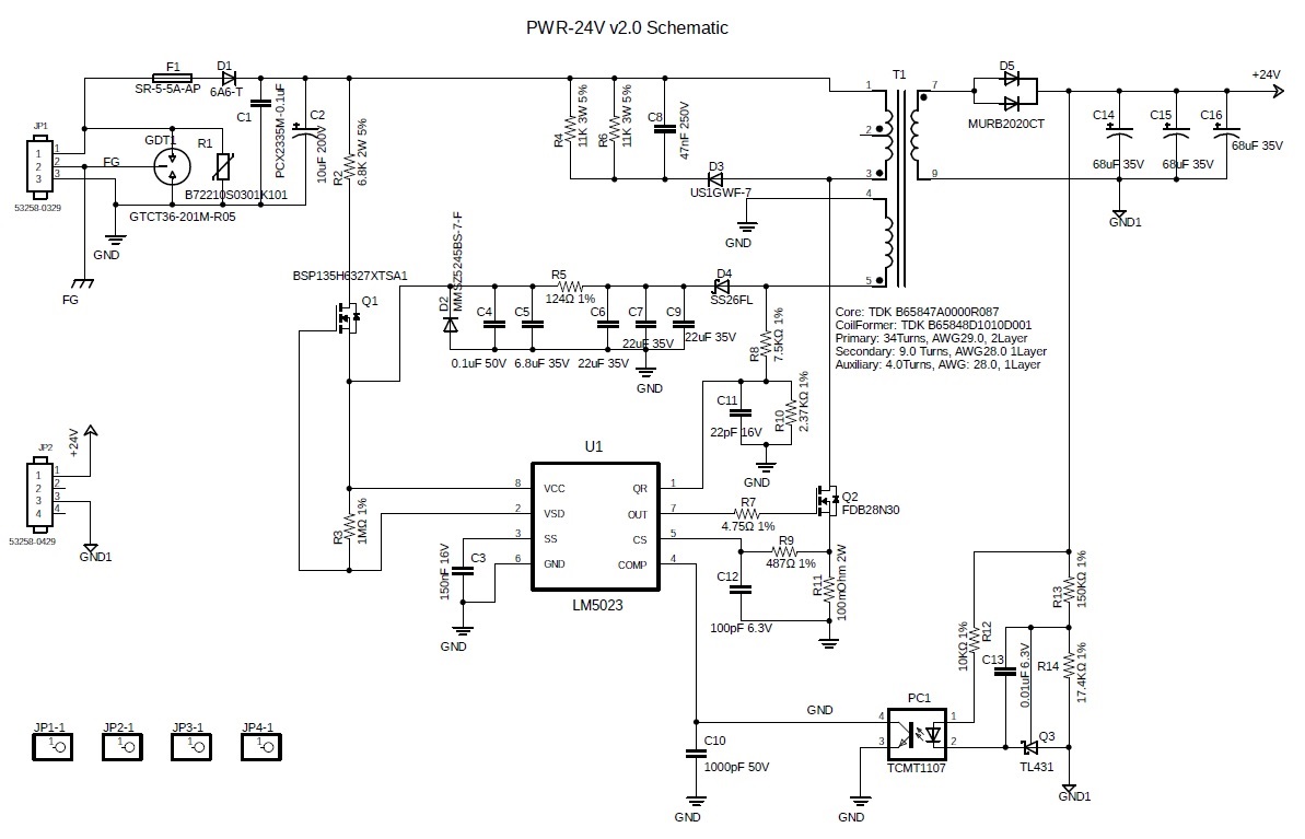
I am attaching it's schematic.

Your help is very appreciated.

Thanks & Regards,

  • Hello,

    I reviewed your schematic and setup around the LM5023 it seems to match the Webench design tool.  The turns ratio that was used is similar to what the tool calculated and should work.  Did you check to make sure the magnetizing inductance of the tool match your transformer?  If not this may cause an issue if it is not the correct size. The design will not work, especially if the inductance is smaller than what the Webench tool calculated.

    I am not sure what the purpose of diode D1 is this is a DC to DC design.  This should still work with a DC input. 

    It may be worth while for you to probe VCC, SS, CS, Comp and QR of the LM5023 to see why the converter is not operating correctly.

    The design could be hitting over current protection (OCP) or over voltage protection (OVP).

    1. If these faults occur switching will stop and the unit will go into VCC hiccup mode.  Please refer to figure 17 in the data sheet.
    2. Please note that noise on the aux winding can trigger an OVP.
      1. OVP can be triggered from TOVP timeout to where Vaux = Vout*Naux/Ns  please refer to figure 12 in the data sheet.

    If the fault is OVP noise it could be resolved by adding RC snubbers across D5 and D4.

    If it is an over current fault due to noise adjusting C12 may help filter the noise.

    Regards,

  • Hello,

    Thanks for your fast reply that is very helpful for me to understand my schematic.

    I did not check the magnetizing inductance of my custom made transformer yet. I will do that in soon.

    The Webbench guided specification was used to make the transformer.

    In this case, Why there is an inductance difference between The Webebbench design and the real transformer?

    Regarding the OVP and OCP that you mentioned, I will try your recommendation.

    Thanks & Regards,

  • Hi seogje,

    Are there any updated?

    Since  I haven’t heard back from you, I’m assuming you were able to resolve your issue. If not, just post a reply below (or create a new thread if the thread has locked due to time-out).

    Thanks,

    Teng

  • Hi!
    At this moment, I am not sure whether I resoled my issue or not. After struggling the transformer modification, I got a little bit of improvement in load capability. (1.2A to 2A)
    Still, I need to study the input voltage range extension.
    If I have any progress, I will update it.
    Thanks & Regards,

  • Hi seogje,

    Hope goes well.

    I am closing this thread now.  if any updated, just reopen it and post a reply below (or create a new thread if the thread has locked due to time-out).

    Regards,

    Teng