This thread has been locked.

If you have a related question, please click the "Ask a related question" button in the top right corner. The newly created question will be automatically linked to this question.

TPS23861: Cascades problem ?

Part Number: TPS23861

Hi TI

We have made an 8-port POE module with 2PCS TPS23861 chip.   


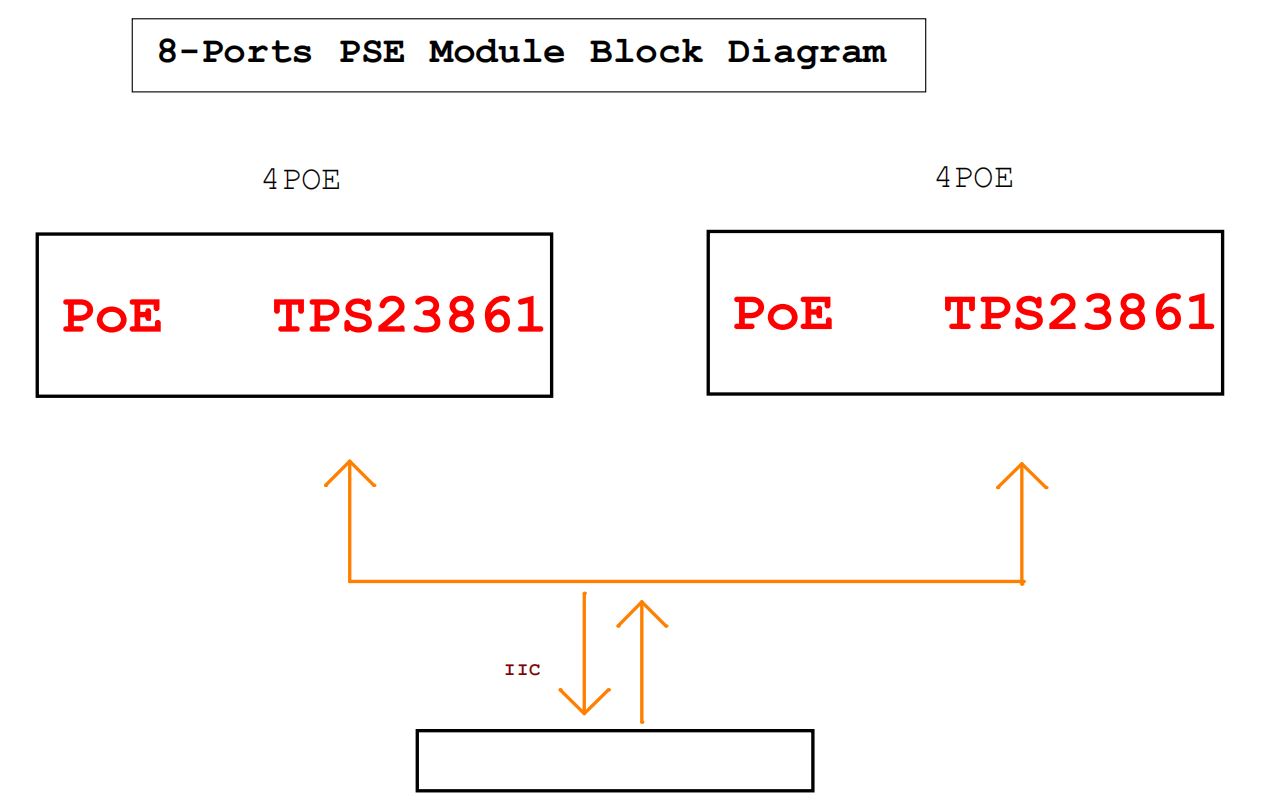
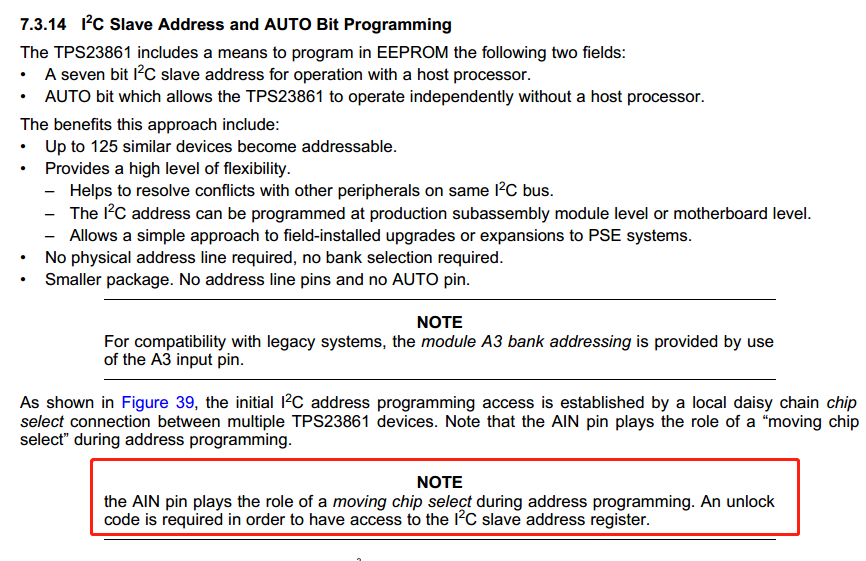
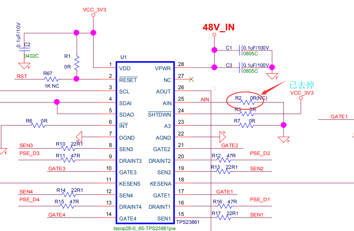
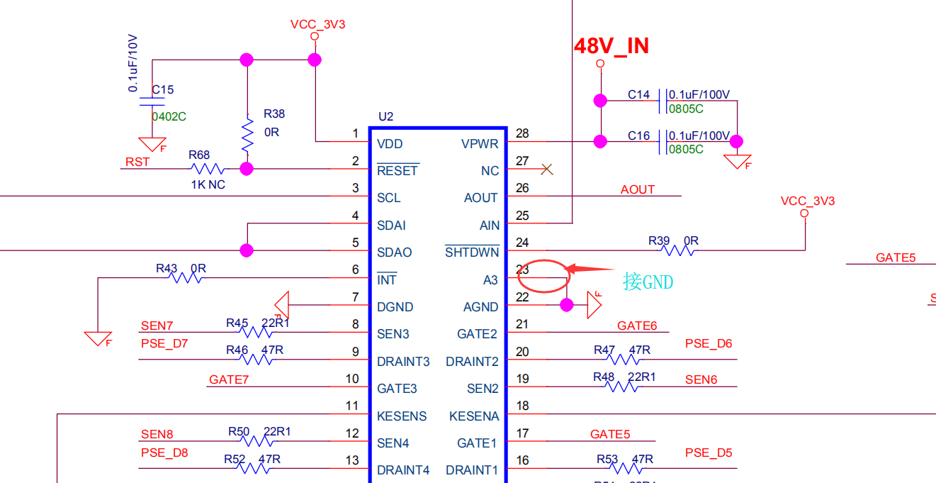
We want to achieve two TPS23861 cascades by changing the circuit. The circuit has made the following changes:

1. The 25PIN of the first TPS 23861 is suspended. Because of its internal pull-up voltage, the AIN is high level. 


2. The 23PIN of TPS 23861 is connected to GND.    


By changing the circuit, software engineers can only read one piece of TPS 23861 through IIC at present.

Now I don't know if there is a problem with the circuit modification or if the software needs to be adjusted. Please give me some suggestions.

Thank you.

Jerry

  • Hi Jerry,

    Did you connect both A3 pins of two TPS23861 devices to GND? If that's the case, two TPS23861 devices have the same default I2C address. The easiest way is to connect one A3 to gnd and the other A3 to VDD. Then you can have 2 different default I2C addresses and you don't need to reprogram the I2C address through software. Please refer to TPS23861EVM-612 for 8 port design. Thanks. 

    Best regards,

    Penny

  • Hi Penny,

    Thank you for your kindly support.

    Our original hardware is to follow the circuit you suggested, the address will be as 0x20, 0x28.

    But our software doesn't need these two addresses. It needs to be modified to something else, such as 0x10, 0x11. 

    So we made some modifications to the hardware as above. At present, we can modify the address of 0x20, but 0x28 can not be modified.

    Are there any suggestions? 

    Thanks.

    Jerry

  • Hi Jerry,

    So you connected both A3 pins are connected to ground and you want to change the address to 0x10 and 0x11, correct? If that's the case, can you please check if you followed the procedure to program the devices' I2C address: https://e2e.ti.com/support/power-management/f/196/p/723203/2668113?tisearch=e2e-quicksearch&keymatch=FAQ%20TPS23861%20I2C#2668113? Thanks.

    Best regards,

    Penny

  • Hi Penny

    Thank you for your kindly support.

    We just refer to this code to write, before not modifying the hardware, has been written unsuccessfully, after modifying the hardware (such as the circuit above) can be modified to 0x20, but 0x28 can not be modified.

    Let's look at the development document 7.3.14 I2C Slave Address and AUTO Bit Programming.

    Are there any suggestions?

    Regards,

    Jerry

  • Hi Jerry,

    I think your AIN, AOUT pin is correct. You connected first device's AOUT to second device's AIN and left first device's AIN and second device's AOUT floating. Can you double check the second device's (0x28) A3 pin status? Is it 3.3V or 0V? If it is connected to 3.3V, you have to program some address with bit 3 to be 1. If you want to program the address to 0x11, you have to make sure A3 pin is 0V. Thanks.

    Best regards,

    Penny