This thread has been locked.

If you have a related question, please click the "Ask a related question" button in the top right corner. The newly created question will be automatically linked to this question.

TPS2121: USB Inrush protection

Part Number: TPS2121
Other Parts Discussed in Thread: TPS22916, TPS56C230, TPS62825

Dear *,

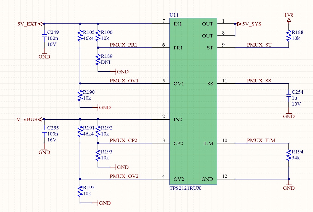
we want to use TPS2121 in a design where our device can be powered from external 5V or USB 5V , ILIM will be set to 3A.

Our device is a USB only device ( Type-C UFP).

As we know we have to have a slew rate limiter on USB VBUS pin because the capacitance is from 1uF to 10uF.

Currently we have VBUS connector pin -> 1uF capacitor -> TPS22916CNYFP ( as slew rate limiter ) -> at the output of the switch TPS22916CNYFP we have 100uF ELCO capacitor.

1)

In new design we want to use TPS2121 for power muxing, but the TPDS2121 also has a SS function , can this function replace the TPS22916CNYFP ?

2) 

can we put only a 1uF to 10uF capacitor on input of TPS2121, it this enough ( max current 3A)? 

can we put a 100uF capacitance or more on the output?

Best Regards,

David.

  • Hi D_zero, 

    Thanks for reaching out on E2E!

    Please find the answers to your questions below:

    1: Yes, the TPS2121 has a soft-start (slew-rate) functionality. Depending on the desired slew rate, you wouldn't need to add the TPS22916 into the circuit. 

    2: It is difficult to determine whether or not 1uF - 10uF is enough to supply 3A without any input voltage dip. This will depend on the strength of your PSU, with a weaker PSU it might not be able to handle the sudden inrush current. In regards to the 100uF output capacitance, this will also depend on your loading conditions and how much VOUT dip the system can tolerate. Larger COUT will result in lower VOUT drop but a higher inrush current, while a smaller COUT will minimize the inrush current but also increase the VOUT dip.

    If possible, I recommend ordering a TPS2121EVM to prototype this configuration. You could test the configuration and adjust the input/output capacitance using your upstream PSU to determine whether not the inrush/dip is acceptable.

    Let me know if you have any questions!

    Thanks,

    Arthur Huang

  • Dear Arthur,

    thank you for the answers, we will order the DEMO, but i have a couple of other questions:

    1)Here is my current schematic without Cin and Cout

    On Cout there is 1x100uF Aluminium CAP, and ~10x10uF ceramic.

    The 5V_SYS connects to 4x TI TPS62825DMQ and 1x TPS56C230

    3A is max current limit.

    a) if we want a Seamless transition and give a priority to IN1 then the CP2 must be grater then VREF 1.06V (V_VBUS/2 = 2.5V, 10k/10k) and PR1 can be direct connected to IN1 ( through 10k)?

    b) Over voltage protection is set to 6V for VREF=1.06V, the TPS62825DMQ ABS max Vin is 6V,  is this ok? or should we use 44k2 so that the 6V is when VREF is 1.1V rising?

    c) Please can you explain Ilm table on page 6, why is there big difference in Iout limit ±500mA for a chosen Rilim?

    What is the right way to chose the Rilm for 3A limit (3A is max operating limit)? Do we need to chose a resistor that covers max limit + inrush current?

    d)Regarding inrush current and tON time calculation,

    I looked at the calculation on DS, but it is not all clear to me.

    - my attention is to limit the inrush from 100mA to maybe 500mA?

    if i calculate SR=Iinrush/CL , lets use 200uF for load and 100mA inrush -> SR=100mA/200uF = 500V/s

    -So i can choose the Css arround 470nF to 1uF for this scenario regarding to table 1 on page 13  is that correct?

    -How can i now calculate the tON or the soft start in ms?

    -Can i calculate approx min Cin for this configuration? I think when there is a transition i can have a voltage dip to 4V because the max voltage in system is 3V3.

    Also i think that the voltage dip is not so critical for our system because we user our system:

    - only USB cable attached, the transition will not occur

    - only external 5V attached, the transition will not occur

    - both cables attached at the power up, external IN1 priority, transition can happen if the AC adapter fails (rare situation, also if USB is 2.0 then there is no enough current to supply the device, not a real scenario)

    -USB attached and device booted and then additional external power provided , transition happens but here we can have larger Cin values, no limitation regarding to USB spec.

    Best Regards,

    David.

  • Hey David, 

    Please find the answers to your questions below:

    a) if we want a Seamless transition and give a priority to IN1 then the CP2 must be grater then VREF 1.06V (V_VBUS/2 = 2.5V, 10k/10k) and PR1 can be direct connected to IN1 ( through 10k)?

    [AH]: Correct, for "fast switchover" you would need to connect CP2 greater than VREF and you could keep PR1 directly connected to IN1.

    b) Over voltage protection is set to 6V for VREF=1.06V, the TPS62825DMQ ABS max Vin is 6V,  is this ok? or should we use 44k2 so that the 6V is when VREF is 1.1V rising?

    [AH]: I'm not familiar with the TPS62825 device, so I can't say for certain which is better. However, as long as you're within the abs max rating of the device it should be ok. You can set OVx to 6V when the pin voltage crosses VREF, correct. 

    c) Please can you explain Ilm table on page 6, why is there big difference in Iout limit ±500mA for a chosen Rilim?

    What is the right way to chose the Rilm for 3A limit (3A is max operating limit)? Do we need to chose a resistor that covers max limit + inrush current?

    [AH]: The ILM pin has built-in hysteresis (±500mA) into the current limit. As you mentioned, this helps to cover the inrush current + normal operating conditions. When you choose a RLIM resistor, it will need to cover the max current limit and the inrush current. See D) for more details:

    d)Regarding inrush current and tON time calculation,

    I looked at the calculation on DS, but it is not all clear to me.

    - my attention is to limit the inrush from 100mA to maybe 500mA?

    if i calculate SR=Iinrush/CL , lets use 200uF for load and 100mA inrush -> SR=100mA/200uF = 500V/s

    -So i can choose the Css arround 470nF to 1uF for this scenario regarding to table 1 on page 13  is that correct?

    [AH]: The calculations look correct based on your requirements. To achieve a slew rate of ~500V/s, a 470nF cap would be a suitable choice.

    -How can i now calculate the tON or the soft start in ms?

    [AH]: Since the slew rate is simply Volts/second, you already have the rise time of the device. Since we selected 500V / S and we're operating at 5V, the rise time is approximately 10ms.

    -Can i calculate approx min Cin for this configuration? I think when there is a transition i can have a voltage dip to 4V because the max voltage in system is 3V3.

    [AH]: Again, I can't say for certain on the CIN calculation. If you have a weaker PSU, the input voltage might dip more during the transition between inputs. As a general recommendation, I would start with 10uF on both inputs and then use the DEMO board to adjust the input capacitance using your upstream power supplies. 

    Thanks,

    Arthur Huang

  • Dear Arthur,

    thank you for the support. Just one question regarding Rilm.

    if we can have at some point Load Current of 3A and if we set the Inrush to 100mA do we then set the current limit Ilm to:?

    a) 3A (load) + 0.1A(inrush) = 3.1A -> Rlim=34k

    b) 3A (load) + 0.1A(inrush) + 0.5A(hysteresis) = 3.6A  -> Rlim=28k5

    Best Regards,

    David.

  • Hi David, 

    I recommend setting the device to the second setting (3.6A). This will give you room for hysteresis + inrush current.

    Thanks,

    Arthur