This thread has been locked.

If you have a related question, please click the "Ask a related question" button in the top right corner. The newly created question will be automatically linked to this question.

LM5164: Part exploding at 70VDC

Part Number: LM5164

Hello,


I have a design that I extracted from Web-bench. During verification of the power supply, when I powered the board with 70V DC the IC exploded at pin 2. I have looked at the Absolute Maximum Ratings and don't see anything the design is violating.  In another instance, the board was working fine at 60V; however, when I increased the load on the supply, the LM5164 also died.  The load current does not exceed 0.4A in worst-case use (actually closer to 0.37A).

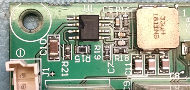
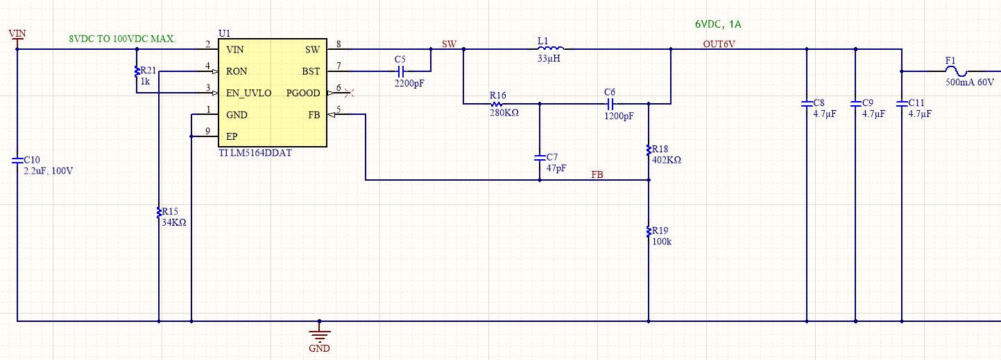
I would appreciate any suggestion.  I'm posting a picture of the failure and the schematic (which like I said, I derived from Web Bench).  Note: the circuit Vin is only supposed to reach ~98VDC in cases of failure and I designed this circuit to withstand this voltage.  In normal operation Vin should be less than 30VDC.


Thanks


  • Hi Diego,

    Please refer to the example layout and the layout guidelines in the LM5164 datasheet.

    It appears that the 1206 input cap is quite far away from the VIN and GND terminals of the IC. Try adding a 0.1uF/100V/0603 cap right at the VIN and GND pins (pins 1 and 2) to achieve absolute minimum connection inductance.

    After that, you may need to review if the parasitic inductance of the input bus wires/traces is resonating with the ceramic input capacitance (in which case you will need to add damping, e.g. electrolytic input cap). Just probe the input voltage behavior, particularly during a load transient, to check this.

    Regards,

    Tim

  • Thanks Tim. I did further testing yesterday and found the issue to be related to the enable pin.  Even though the typical application circuit shows EN/UVLO directly connected to VIN, I read in section 7.3.9. that "TI recommends selecting Ruv1 in the range of 1MΩ for most applications". I changed the 1KΩ resistor in my circuit with a 700kΩ (highest I had) and this solved the issue: I was able to cycle power with full load/low load at 100V Vin.  

  • Hi Diego,

    Please check the voltage applied to the EN/UVLO pin. The datasheet statement is only to minimize quiescent current when the pin is pulled low. The resistor value should not impact reliability, but I suspect the larger resistor value and pin capacitance are creating an RC filter that is attenuating an applied overvoltage.

    Regards,

    Tim