This thread has been locked.

If you have a related question, please click the "Ask a related question" button in the top right corner. The newly created question will be automatically linked to this question.

TPS62748: Maximum inductance

Part Number: TPS62748
Other Parts Discussed in Thread: TPS62740, , TPS62840, TPS62175

Hi,

for the TPS62748, there are no limits for the inductance in comparison to other devices like TPS62740 where the recommended maximum inductance is 3.3 uH. What is the maximum inductance for the TPS62748? I'd like to increase it as much as possible to decrease output ripple.

Regards,

Jonas

  • Hi Jonas,

    The allowed inductance (and its range) is shown in Table 3.

    What is your ripple target/spec?  This reference design shows the common way to get low ripple, with an LDO after the DC/DC: http://www.ti.com/tool/TIDA-01566

    As well, make sure you check out our new 60 nA buck, TPS62840.

  • Hi Chris

    We need to get below 1 mVp-p ripple with the requirement to run on a 3 V coin cell battery where the battery voltage ranges down to ~2.0 V. Iq requirement maximum 500 nA. Maximum current peaks are below 100 mA. With an additional LC filter after either TPS62740 or TPS62748, it should be possible to achieve this if the buck can handle a post LC filter. However, output ripple is very dependent on buck inductor so we would like to increase this to a maximum.

    We have ordered the evaluation hardware for the new TPS62840, but we do not know of availability and time schedule as this buck converter has not been released yet.

    Regards,

    Jonas

  • Thanks for explaining.

    At what frequency do you need < 1 mV ripple?  To have good efficiency, all these devices will be in power save mode with a lower frequency of pulses.

    The TIDA above is really optimized for this case, since the LDO has very high PSRR at a low frequency.  You can see the waveforms in the design guide--all ripples are well below 1 mV.

    What is your output voltage?

    The TPS62840 should be fully released soon.  And it is fully on the web, with samples and EVMs available.  If there is something you need for it, let me know.  If you have a very light load (as I expect you do), it will extend your battery life.

    Thanks for ordering the EVMs and experimenting with these.  You should keep the main inductor as 2.2uH but can add a second filter.  I'm not sure how effective it will be, considering the low frequency in PFM.

  • Output voltage is 1.8 V. We have the following ripple specification:

    10 kHz: 18.7 mVpp

    100 kHz: 2.6 mVpp

    1-10 MHz: <1 mVpp

    >100 MHz: < 3 mVpp

    These are only required for currents above 5 mA or so.

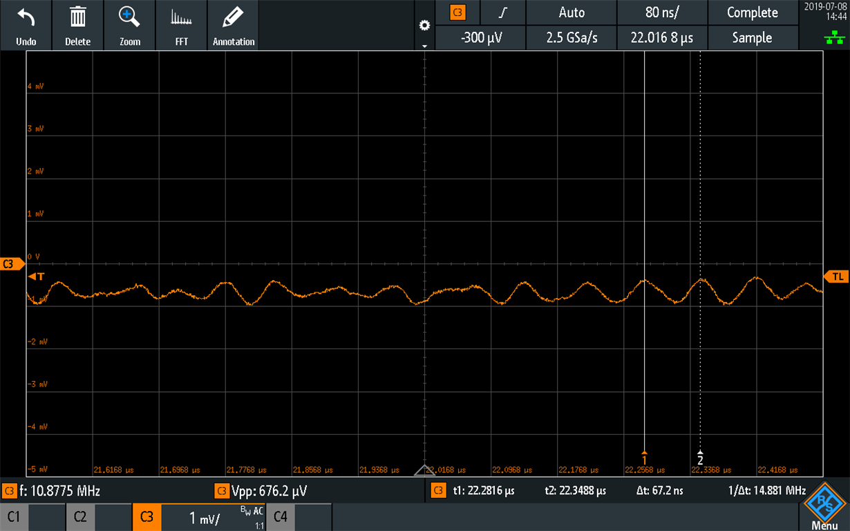
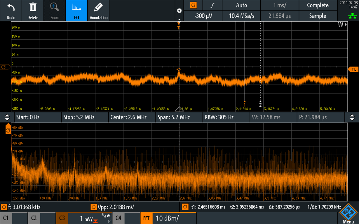
    For the TPS62740 EVK, and after increasing inductor size to 3.3 uH and adding a post LC filter (with damping) the HF ripple (~14 MHz) is below 1 mVp-p. There is some lower frequency ripple that may be of concern. We would like to investigate if it is possible to achieve low enough ripple without adding an LDO.

    Output voltage plots:

  • Thanks for explaining.  It sounds like your second filter allows you to meet your spec?

    Equation 3 in the TPS62175 D/S shows where the PFM frequency will be for a single pulse PFM system, like DCS-Control.  This can estimate where the fundamental frequency is for your conditions.

    In case you are interested, here is a technical article on designing these second stage filters: https://e2e.ti.com/blogs_/b/powerhouse/archive/2018/01/18/design-a-second-stage-filter-for-sensitive-applications

    Finally, for the TPS6274x, be sure and connect the Vout pin after the first inductor and not after the second filter.  This will give some load regulation across the second filter, but this should not be an issue with your low currents.