Dear Team,
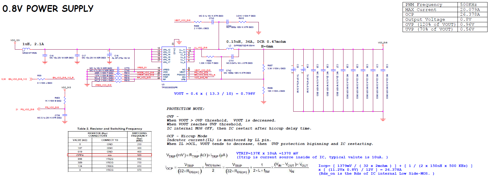
Here is the TPS53355 schematic.
Can you help on final review?
Feel free to drop me a mail if necessary : a0235746@ti.com
BR
Kevin
Dear Team,
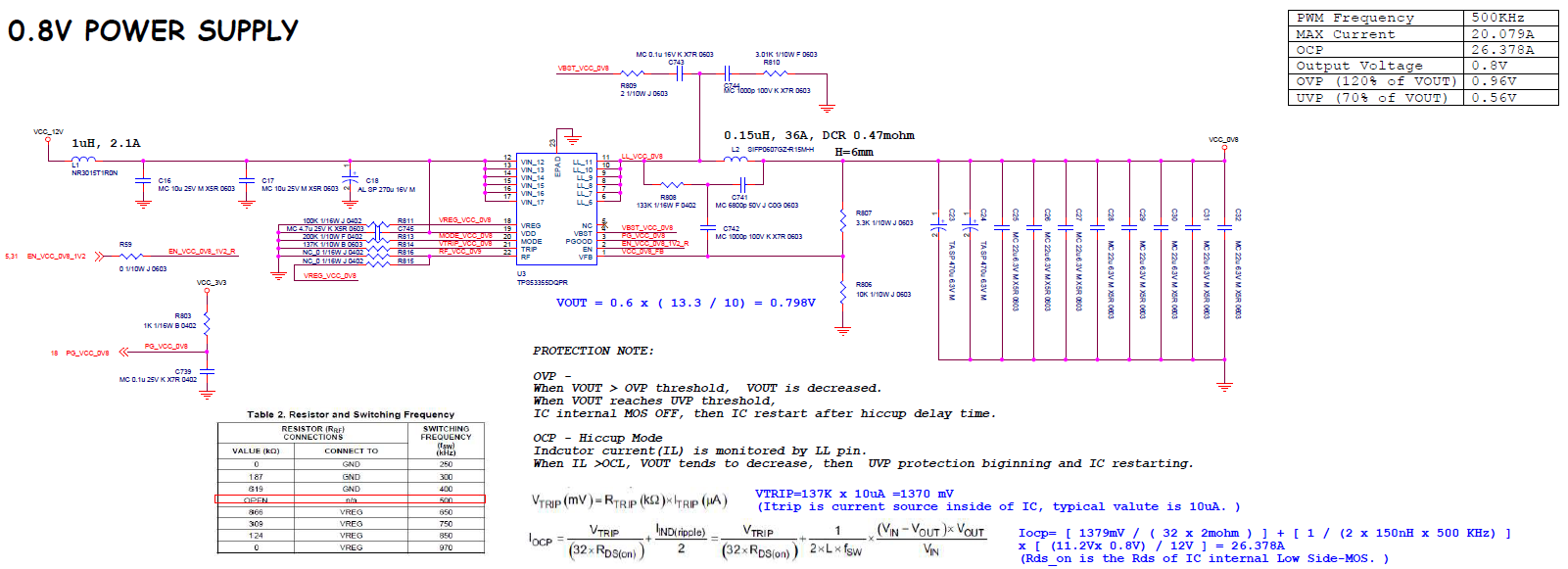
Here is the TPS53355 schematic.
Can you help on final review?
Feel free to drop me a mail if necessary : a0235746@ti.com
BR
Kevin