This thread has been locked.

If you have a related question, please click the "Ask a related question" button in the top right corner. The newly created question will be automatically linked to this question.

LM74700-Q1: Replacing PFETs with Ideal Diode

Part Number: LM74700-Q1
Other Parts Discussed in Thread: TPS62135, BQ2057,

Good afternoon...

I'm looking at a low loss way to connect a buck converter to a battery charger....Initially I was using a diode and found it to waste too much power....I have been considering placing low RDSon MOSFETs (P type) back to back and using them however I have also been looking at the LM74700 ideal diode....After reading the datasheet I just want to confirm what I believe I read:

1.  The reverse leakage current will be caused by IDSS due to inherent body diode?  I have a high impedance resistive feedback on buck converter so this leakage is important to me.....

2.  At turn on inrush will be through the body diode until mosfet turn on?

3. In the event the MOSFET gets disabled (via the Enable pin) the body diode WILL conduct all the current?

Thanks

Steve 

  • Hello Steve,

    Reverse leakage:

    Yes, reverse leakage current is mainly through the external MOSFET inherent IDSS as the MOSFET is turned off with Gate-Source voltage made 0V.

    In addition to the MOSFET IDSS, the leakage through the IC from C pin is about 2.06uA maximum and this is specified in datasheet electrical table in page 6.

    Inrush:

    During the initial turn on of the MOSFET, body diode will conduct the inrush current until the gate is turned on.

    Disabled:

    When disabled via EN pin, body diode of the MOSFET will still conduct in the forward direction.

    Are you looking for  back to back MOSFET connection?

    Regards,

    Kari.

  • Hello Kari,

    I'm not sure. Currently the divider on the buck TPS62135 is about 1.3M ohms which is light enough that the leakage current when the diode is off causes the voltage to increase on the output....This voltage then feeds back thru the TPS MOSFET body diode onto the Vin / En pin....Also the when the diode is on the losses on this small design are causing heat issues...I want to move to a low loss interconnect between the TPS and the BQ2057 battery charger...My initial thought was back to back P-FETs....The ideal diode things sounds promising but I heard rumblings from a peer that first time power up where Vout may be a voltage (ie in my case tied to a battery) and you THEN apply Vin that there may be some issues??  Can you comment on anything that I may want to be aware of for my application?

    Thanks

    Steve

  • Hello Steve,

    Please give me some more time to look at your response and get back.

    Regards,

    Kari.

  • Hello Steve,

    When LM74700-Q1 is off, leakage from cathode (drain of MOSFET) to anode (source of MOSFET) is due to the IDSS leakage of the MOSFET (usually manufacturers specify it to be 100nA range). 

    2uA leakage mentioned in datasheet is from Cathode to GND and this is not expected to impact your design.

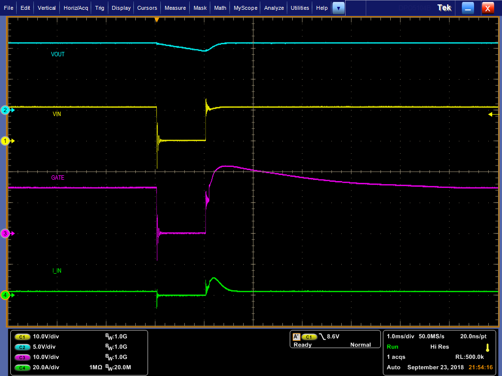
    Regarding the concern raised by your peer, there is no issue in LM74700-Q1 turn on with its OUTPUT (Cathode) powered already.

    Refer to the attached picture (VIN is Anode, VOUT is cathode).

    Regards,
    Kari.

  • Thanks Kari.....

    So at 20A / Div I will have to take your word on leakage current  when Vin (Anode) is off and Cathode is hot as it is hard to tell from C4. A few questions:

    1.  When the anode is > cathode (I'm guessing switch is off here??) then common cathode current is 2uA to ground per datasheet?

    2.  What specification in the datasheet leads me to recognize leakage current from cathode to anode? (Is this part of Ishutdown which is 900nA?)

    Steve

  • Hi Steve,

    Above waveform is it indicate that the part does not have any issue in turning on when cathode is powered or has some voltage potential. (You had a question based on peer experience). This is not an indication of leakage.

    1. When Anode is < cathode (by 100mV) datasheet specifies the leakage from cathode is 2.2uA maximum.

    2. When Cathode is 12V and anode is -12V, then the maximum leakage is 2.06uA.

    Regards,

    Kari.

  • Hi Steve,

    Adding to the above response, when anode is -12V, cathode leakage to GND does not exist. This is because GND connection is open to protect from reverse -12V. So this leakage of 2.06uA maximum is from cathode (12V) to anode (-12V). But however this is not what you are asking.

    But you require leakage current when cathode is powered and anode is 0V?

    Regards,
    Kari.

  • Hi Kari....

    I want to use this device between a Buck converter and a battery charger.

    I believe from the datasheet that if I "turn off" (ie take the Enable pin low) the active diode then my maximum leakage current is 1.5uA (I(shdn) from spec sheet), independent of Vcathode and Vanode.  Does that sound correct?

    thanks

    Steve

  • Hello Steve,

    Yes my understanding is that you are using ideal diode between buck converter and batter charger and the initial concern was that when ideal diode is turned off and buck is also off, leakage from battery charger side through ideal diode should not accidentally turn on due to few uA of leakage through 1.3Mohm resistor divider (feedback path of buck). If this leakage was higher enough to incease to few Volts (3-4uA could lead to 5V) and this 5V output of buck can further turn on the buck through its high side MOSFET body diode. Let me know if i understand the problem correctly?

    Back to I_Shdn, yes it is 1.5uA maximum when EN is low.

    Regards,

    Kari.

  • Kari....

    Yes you do understand the problem correctly!  I believe you have answered me as well...At the end of the day I am not sure of all the mechanisms that may be going on but want the lowest possible leakage current and it sounds to me like 1.5uA is it from our discussion.  Certainly this is a good number....Of course I still may have to contend with the fact that the anode looks like an open circuit and in practice if you put a voltage on one end of a diode (cathode or anode) with no load on the other the voltage will reside on the other end of that diode (anode or cathode), as it will just lift the diode above ground that particular voltage on both ends.  This in turn will feed back through the internal MOSFET body diode of the BUCK to the Vin pin (which I have and do see on my traditional diode I used).  My thought here would be however if it tried to turn it on then the diode would be reversed bias and NOT support the current requirements of the BUCK starting up hence converter stays off.

    Anyway thank you as I believe you have answered my initial question.....

    Steve